Diagrams have been used since ancient times on walls of caves but became more prevalent during the Enlightenment. Component diagrams Deployment diagrams.
Component Diagram Tutorial
Undermentioned are little- and well-known facts about the human body.

Component diagram nedir. Deployment diagrams is a kind of structure diagram used in modeling the physical aspects of an object-oriented system. Type attribute value lines show field references Class diagram. Steering Knuckle Control Arm Ball Joint.
A graph or chart To represent or indicate something using a diagram n a mathematical scheme figure plan. Connectors Aggregation or composition association dependency or generalization3. It is certainly the most widely studied structure the world over.
Deployment diagrams are made up of several. The word graph is sometimes used as a synonym for diagram. Package diagrams are used to structure high level system elements.
What is class diagram in UML. I got the idea of portlib on the providing interface side. Also known as the Unified Modeling Language UML helps in seamless designing and diagramming of the systems in a number of ways.
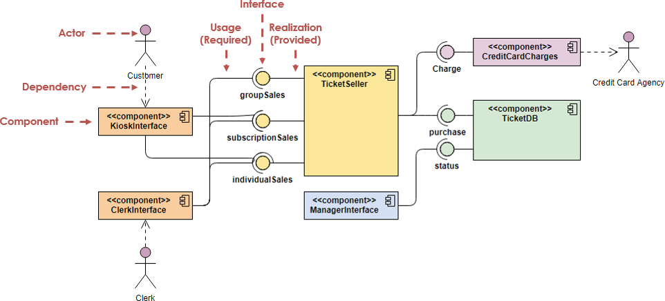
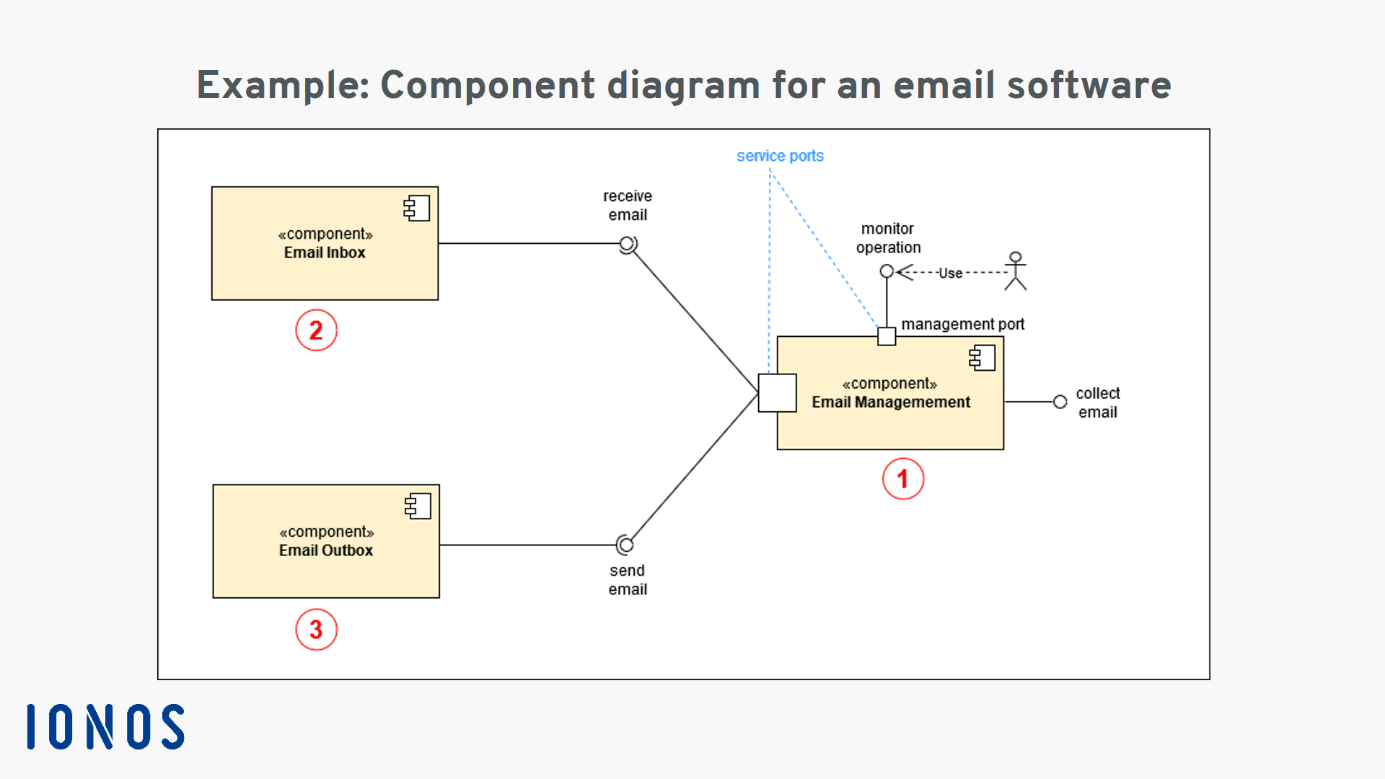
A diagram is a symbolic representation of information using visualization techniques. So far in my books I have only seen use-dependencies between a component and an interface box notation not a lollipop -- reg ports. The human body is one complex network universally accepted as the most intriguing construct.
Use the following properties to create a shape template. Component-level design defines the data structures algorithms interface characteristics and communication mechanisms allocated to each component for the. Diagrams teriminin İngilizce İngilizce sözlükte anlamı plural of diagram Drawings that are used to show wiring vacuum or hydraulic systems third-person singular of diagram Cast your mind back to the days when your science teacher would set you targets at the end of your homework asking you to do diagrams in pencil use a ruler use lots of space on the page label it fully well.
A package is a collection of logically related UML elements. Refactor Design And Consider Alternatives. The schematic collection can be a powerful tool for creating modifying and maintaining any software.
Packages are used for organizing large system which contains diagrams documents and other key deliverables. SysML diagrams and language concepts How to apply SysML as part of a model based SE process Basic considerations for transitioning to SysML This course is not. That are object name attributes and processes or functions belongs to the object2.
Package Diagram can be used to simplify complex class diagrams it can group classes into packages. Object diagram class diagram individual objects heap layout objectName. We would like to show you a description here but the site wont allow us.
The information that the software generates is called an artifact. It is a set of instructions for transforming a software project by generating or modifying code. Very big but a nice standard that has been embraced by the industry.
The event-driven architecture pattern is a popular distributed asynchronous architecture pattern used to produce highly scalable applications. Posted in Diagrams Women Tagged female anatomy female body. Class Diagram consist of1.
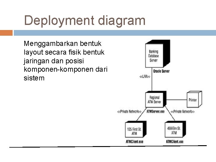
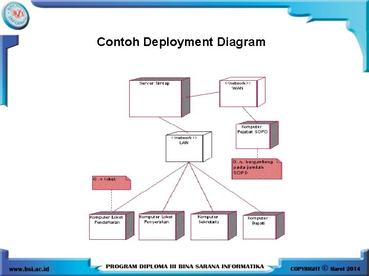
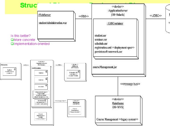
Deployment diagrams help model the hardware topology of a system compared to other UML diagram types which mostly outline the logical components of a system. In this case the deployment diagram describes the physical deployment of information generated by the software program on hardware components. Intended to make you a systems modeler.
Teriminin İngilizce İngilizce sözlükte anlamı diag A plan drawing sketch or outline to show how something works or show the relationships between the parts of a whole. In simpler words it lets an engineer or a developer get a standard way to visualize the overall design of the system. This diagram depicts Picture Of Female Reproductive System Diagram 10241204 with parts and labels.
Template content must be presented as SVG elements. A UML deployment diagram is a diagram that shows the configuration of run time processing nodes and the components that live on them. Event-Driven Architecture - Software Architecture Patterns Book Chapter 2.
Sticking to the Instrumentation Systems and Automation Society ISA S51 Instrumentation Symbols and Identification standard ensures a consistent system independent means of communicating instrumentation control and automation intent so. It is also highly adaptable and can be used for small applications and as well as large complex ones. Component level design is the definition and design of components and modules after the architectural design phase.
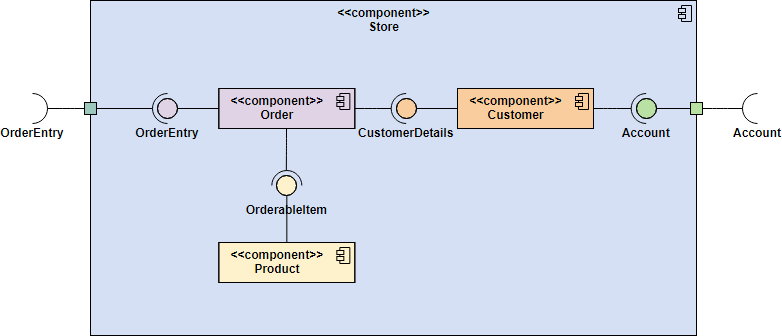
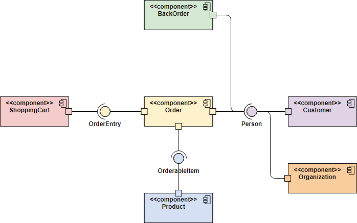
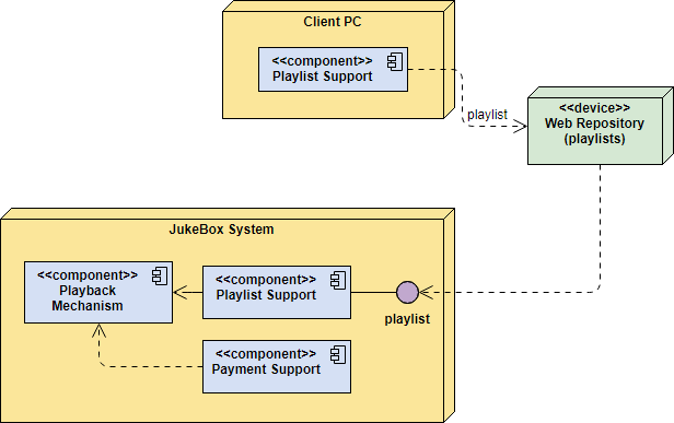
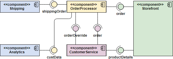
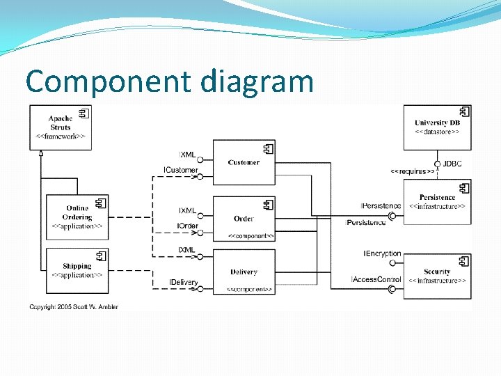
Deployment Diagram Notations In order to draw a deployment diagram you need to first become familiar with the following deployment diagram notations and deployment diagram elements. They are often be used to model the static deployment view of a system topology of the hardware. Component diagram displays the structural relationship of components of a software system.
Practicing Systems Engineers interested in system modeling. Picture Of Female Reproductive System Diagram 10241204 Diagram - Picture Of Female Reproductive System Diagram 10241204 Chart - Human anatomy diagrams and charts explained. Yet in my 1st diagram MsgGenerator has a port then the requiring interface then the delegate then another port then the interface again.
For those who arent aware let us first clarify what UML is. Instrumentation symbols appearing on diagrams adhere to ANSIISAs S51-1984 R 1992 standards. A schematic is a template-based code generator that supports complex logic.
The Diagram UI component allows you to create templates for shapes and their presentation in the toolbox. Elaborate Deployment Diagrams 7. Sometimes the technique uses a three-dimensional visualization which is then projected onto a two-dimensional surface.
This shouldnt be confused with the use of the term in other modeling approaches like BPMN. Electrical diagrams show device interconnections. Suspension System Suspension System Functions Suspension System Components.
Schematics are packaged into collections and installed with npm. A Component that has three sections.
Cbse 2014 Modeling Components With Uml 2 Exercises
1 Unified Modeling Language Uml By U Abd
Component Diagram Tutorial

Component Diagram Tutorial Lucidchart
Pertemuan 2 Uml Uml Unified Modeling Language Adalah
Uml Component Diagram Explanation Drawing And Example Ionos
Modeling Language Uml 1 System Analysis Design Course
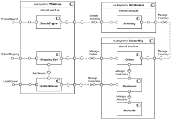
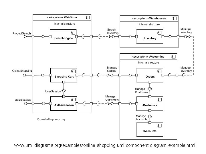
Uml Component Diagram Examples Online Shopping Subsystems And Components Sentinel Hasp Licensing Components

Component Diagram Tutorial Lucidchart
Component Diagram Tutorial

Object Modeling With Omg Uml Introduction To Uml

Object Modeling With Omg Uml Introduction To Uml
Component Diagram Tutorial

Deployment Diagram Tutorial Lucidchart
Component Diagram Tutorial

Component Diagram Tutorial Lucidchart
Uml Diagrams Unified Modeling Language What Is Uml
Component Diagram Tutorial
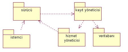
Uml Ile Bilesen Component Diyagramlari


0 Comments