Source code program perangkat lunak. Diagram komponen juga dapat digunakan untuk memodelkan hal-hal berikut.
2
Basic Concepts of Component Diagram.
Component diagram simbol. Atau hal-hal fisik dari sistem yang akan dimodelkan dan ada ketika sistem dieksekusi. Electrical symbols and electronic circuit symbols. A component is a logical unit block of the system a slightly higher abstraction than classes.
To illustrate dependencies between the two use a solid line with a plain arrowhead joining the. UML Deployment Diagram Shapes Package is used to group elements and to provide a namespace for the grouped elements. Basics 11 MOV Schematic with Block included Basics 12 12-208 VAC Panel Diagram.
Basics 6 72 kV 3-Line Diagram. Basics 13 Valve Limit Switch Legend. Basics 10 480 V Pump Schematic.
Jadi Diagram komponen atau component diagram dibuat untuk mengambarkan struktur dan ketergantungan antara kumpulan komponen dalam sebuah sistem. Diagram komponen atau component diagram dibuat untuk menunjukkan organisasi dan ketergantungan diantara kumpulan komponen dalam sebuah sistem. To design a Component Diagram use the UML Component Diagram.
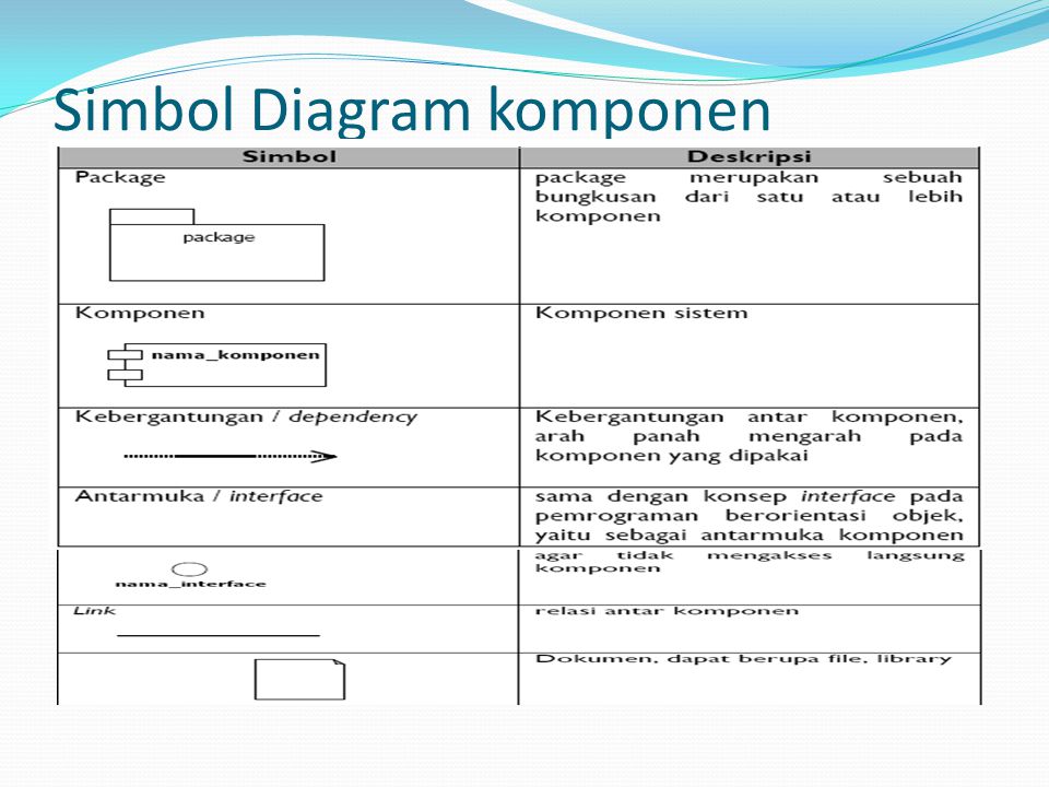
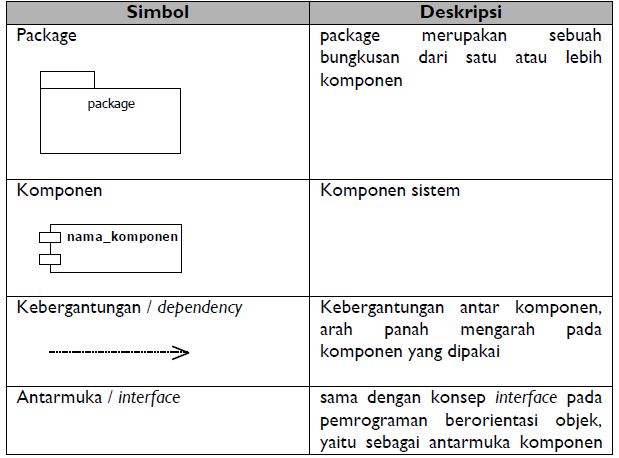
1 Rectangle with the component stereotype the text. A component defines its behavior in terms of provided and. 123 Component Diagram 1231 Component Sebuah komponen digambarkan dengan segiempat dimana pada bagian atas diberi label component.
Pneumatic Symbols For system diagrams and component identification Contents z Standards z Actuators z B i symbols Basic b l z V l symbol Valve b l structure t t z Functional elements z Valve functions z Flowlines z Three position valves z Connections z Operators z Conditioners and plant z Port marking z Pressure regulators z Function components z Relief valves z Symbol Library Click the. UML Component Diagram Symbols UML Component Diagram Shapes. COMPONENT NOTATION A component is shown as a rectangle with A keyword Optionally in the right hand corner a component icon can be displayed A component icon is a rectangle with two smaller rectangles jutting out from the left-hand side This symbol is a visual stereotype The component name Components can be labelled with a.
UML deployment diagram symbols like package object node component node instance component instance interface inheritance and more are available. Component diagrams range from simple and high level to detailed and complex. Inherited interfaces may be shown with a lollipop preceding the name label with a caret symbol.
It is important to note that the internal components are surrounded by a large box which can be the overall system itself in which case there would not be a component symbol in the top right corner or a subsystem or component of the overall system in this case the box is a component itself. Basic Component Diagram Symbols and Notations Component. The component diagram extends the information given in a component notation element.
We have explained below the common component diagram notations that are used to draw a component diagram. Rapid UML Solution for ConceptDraw DIAGRAM contains 13 vector stencils libraries with 393 interactive shapes that you can use to design your UML diagrams. At first these diagrams might look like any other flowchart but they have dedicated ER diagram symbols that define the overall connectivity structure and relationship in a database.
Basics 9 416 kV Pump Schematic. Basics 14 AOV Schematic with Block included. UML Component Diagram illustrates show components are wired together to larger components and software systems that shows the structure of arbitrarily complex systems.
Basics 7 416 kV 3-Line Diagram. Label bisa diberi nama dengan menggunakan stereotypes standart antara lain. Diagram komponen fokus pada komponen sistem yang dibutuhkan dan ada didalam sistem.
The following are shape types that you will commonly. Component Diagram Symbols. Covering the Basics The ER relationship modeling was devised by Peter Chen in the 1970s and has witnessed a few minor changes in the present time.
Demikian pembahasan tentang Pengertian Component Diagram. Component diagram shapes and symbols. The component stereotype is usually used above the component name to avoid.
There are three ways the component symbol can be used. Fungsi Simbol dan Contohnya. UML component diagram symbols like component package package container dependency generalization tranparent stereotype opaque stereotype note and more are available.
107 rows Electrical Symbols Electronic Symbols. Component represents a modular part of a system. Either way youll want to familiarize yourself with the appropriate UML symbols.
Pada bagian kanan atas terdapat icon component yang dapat ditampilkan ataupun tidak ditampilkan. Basics 8 AOV Elementary Block Diagram. It is represented as a rectangle with a smaller rectangle in the upper right corner with tabs or the word written above the name of the component to help distinguish it from a class.
September 2017 Mengenal Teknologi Sistem Informasi Komputer


Bab Iv Tinjauan Pustaka

Si1512484723 Widuri
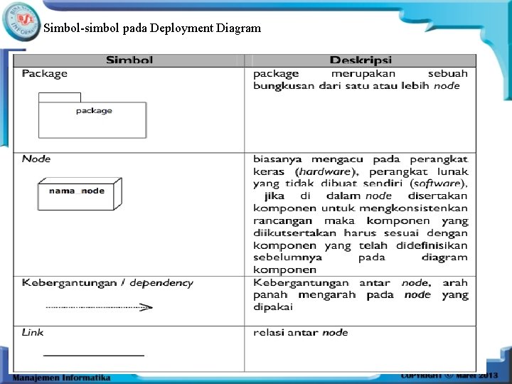
Simbol Deployment Diagram Dan Fungsinya

Pengertian Class Diagram Fungsi Simbol Dan Contohnya Ansori Web

Tap Com Sistem Informasi Pendistribusian Produk Pada Pd Stmik Mdp

Simbol Deployment Diagram
Si1512484723 Widuri

5 Contoh Class Diagram Disertai Pengertian Dan Simbol
2

Usaha Masa Kini Simbol Simbol Diagram Alir Uml
Apa Itu Component Diagram Mengenal Component Diagram
Pertemuan 12 Package Diagram Deployment Diagram Deployment Diagram
2

Rekayasa Perangkat Lunak Deployment Diagram Dwi Nurani 12 51 0302

Blok Pembangun Uml Adesta2008 S Uml

5 Contoh Use Case Diagram Dilengkapi Simbol Dan Komponen

Simbol Dari Deployment Diagram Adalah
Si1512484723 Widuri


0 Comments