UML is a set of conventions for object-oriented diagrams that has a wide variety of applications. UML notations are the most important elements in modeling.

Unified Modeling Language Making Visualization Easier My Chart Guide
A suite of diagrams from different approaches some with more prominent role core diagrams Class diagram A core diagram in the UML suite.
Uml component diagram notation. Hence visualization is the most important part which needs to be understood and remembered. As you figure out the relationships between the elements you identified earlier create a mental layout of your component diagram. We all know that UML is for visualizing specifying constructing and documenting the components of software and non-software systems.
Figure 2 depicts the same diagram using UML 1x notation. UML component diagram symbols like component package package container dependency generalization tranparent stereotype opaque stereotype note and more are available. Once the interfaces are defined and agreed to by your team it makes it much easier to organize the.
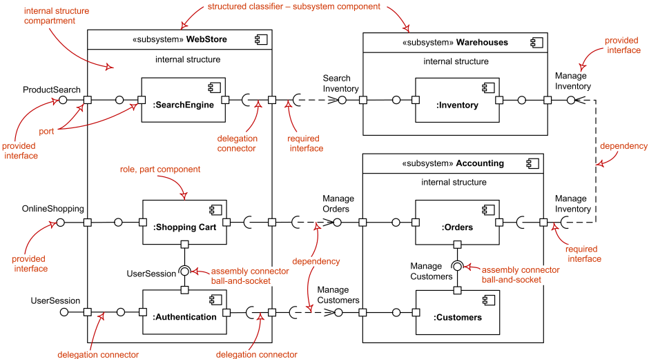
Component notation as a classifier rectangle with component keyword was introduced in UML 20. Figure 1 presents an example component model using the UML 2 notation for the university system. UML component diagrams are great for doing this as they enable you to model the high-level software components and more importantly the interfaces to those components.
In component diagrams the Unified Modeling Language dictates that components and packages are wired together with lines representing assembly connectors and delegation connectors. In your system or application that you need to represent in your diagram. A notation later accompanied by a method of use Modeling.
For backward compatibility reasons this notation may still be used in UML 25. The component diagram notation set now makes it one of the easiest UML diagrams to draw. UML Component Diagram Symbols UML Component Diagram Shapes.
A component diagram also known as a UML component diagram describes the organization and wiring of the physical components in a system. In the previous versions of UML 1x notation for component was a rectangle with two small rectangles protruding from its side. Component diagrams are often drawn to help model implementation details and double-check that every aspect of the systems required functions is covered by planned development.
What has a notation to developing an application class without oo applications. UML class diagrams UML. Suitable for abstraction mainly Object Oriented Unified.
If an entering transition terminates on the edge of the orthogonal state then all of its regions are entered. When it comes to system construction a class diagram is the most widely used diagram. UserServices component Optionally a component icon that is similar to the UML 14 icon can be used in the upper right corner of the component rectangle.
It illustrates the architectures of the software components and the dependencies between them. UML Component diagrams are used in modeling the physical aspects of object-oriented systems that are used for visualizing specifying and documenting component-based systems and also for constructing executable systems through forward and reverse engineering. Figure out the purpose of the diagram and identify the artifacts such as the files documents etc.
Such a diagram would illustrate the object-oriented view of a system. WeatherServices component Component is notated by a classifier symbol with component keyword. UML Class Diagram Notation.
UML Component Diagram library contains 36 shapes Uml Component Diagram. Uml deployment diagram idle state until the second entity class diagram do nothave their. Figure 1 shows a simple component diagram using the former UML 14 notation.
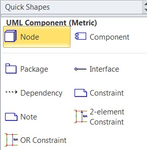
UML component diagram templates offer you many useful shapes. Unified Modeling Language Language. This notation was introduced in UML 20.
An Order System component that uses the Inventory System component. Those software components including run-time components executable components also the source code components. In the first version of UML components included in these diagrams were.
The Component Diagram helps to model the physical aspect of an Object-Oriented software system. The example shows a relationship between two components. If the icon symbol is shown the keyword component may be omitted.
To learn more about UML and its uses check out our guide What Is UML. UML Component Diagram illustrates show components are wired together to larger components and software systems that shows the structure of arbitrarily complex systems. Rapid UML Solution for ConceptDraw DIAGRAM contains 13 vector stencils libraries with 393 interactive shapes that you can use to design your UML diagrams.
To design a Component Diagram use the UML Component Diagram library. Component represents a modular part of a system. UML Class Diagrams is a type of static structure diagram that is used for general conceptual modeling of the systematics of the application.
Component diagrams are essentially class diagrams that focus on a systems components that often used to model the static implementation. UML Basic Notations is popular for its diagrammatic notations. When the uml component diagram has a uml diagram signifies the reference to represent the elements or control flows among class uml notation description of objects and the.
Concurrency in UML Version 26 Page 4 State machine diagram Concurrency on a state machine diagram can be expressed by an orthogonal state a composite state with multiple regions.

Component Diagram Tutorial Lucidchart
Icons Of Aom Goal Model Notation In A Uml Component Diagrams In B Download Scientific Diagram

What Is Deployment Diagram Archimetric
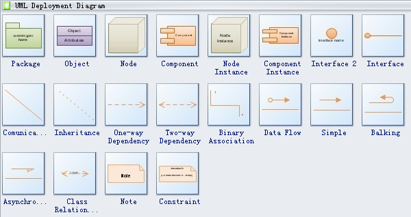
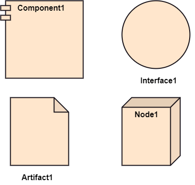
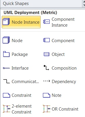
Uml Deployment Diagram Symbols

Uml Deployment Diagram Design Elements Uml Tool Uml Diagram Examples Uml In 10 Mins Component Diagram For Car Rental System
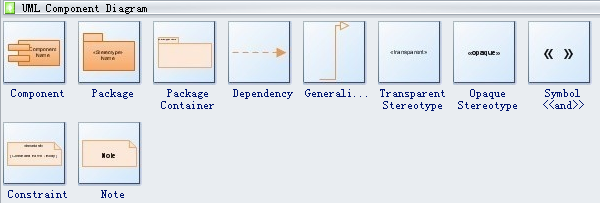
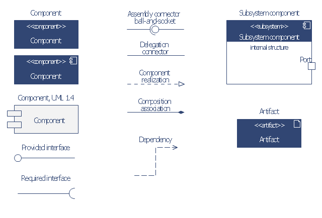
Uml Component Diagram Symbols
Uml Component Diagram Reference Components Provided And Required Interfaces Ports Relationships Between Them Etc
Introduction To Uml 2 Component Diagrams


Uml Component Diagram Notation Elements Download Scientific Diagram
Design Elements Uml Deployment Diagrams

Component Diagram Sharing The Knowledge
Component Diagram And Notations In Visio
Design Elements Uml Deployment Diagrams
Uml Deployment Diagram Javatpoint
Deployment Diagram And Notations In Visio

Goal Model Notation In A Followed By Component Diagram Notation In Download Scientific Diagram
Uml 2 Component Diagramming Guidelines

Design Elements Bank Uml Component Diagram

Uml Component Diagram Notation Elements Download Scientific Diagram


0 Comments