A special kind of class diagram that focuses on a systems nodes. System and subsystem diagram d.

King Chess Game Design Components Diagram Component Diagram Diagram Game Design
Architectural class diagram c.

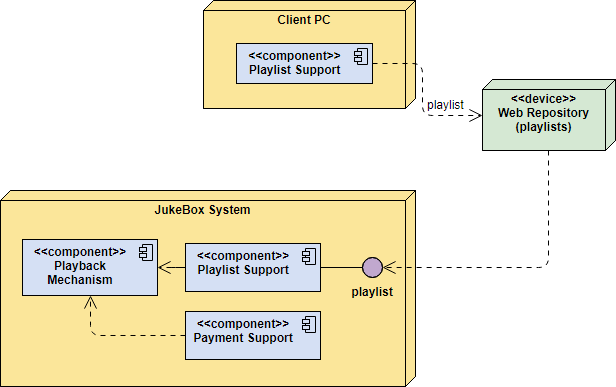
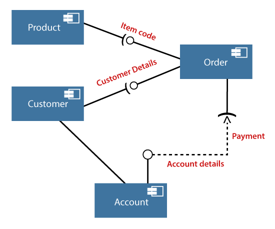
Component diagram is a special kind of _ _ _ _. Polar wander QUTOJ uenury ue uue statement associateu wiun uS dlagram North America 180 90 E. This is a Component diagram of Hostel Management System which shows components provided and required interfaces ports and relationships between the Allotees Rooms Beds Hostel Facility and Rent. Use case diagram D.
It allows you to visualize the hardware topology system model physical hardware elements and the communication relationship between them and plan the architecture of the system. However every x-value must be associated to only one y-value. A component diagram is similar to a class diagram in that it illustrates how items in a given system relate to each other but component diagrams show more complex and varied connections that most class diagrams can.
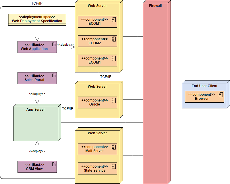
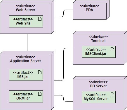
A deployment diagram is a diagram that shows the configuration of run time processing nodes and the components hardware software middleware on hardware that live on them that is used to model the static deployment view of a system topology of the hardware. They are often be used to model the static deployment view of a system topology of the hardware. Hostel Management System UML component diagram describes the.
Different Types of Electrical Diagrams and Drawing. A use case diagram will show the series of steps involved in the implementation process of a system. A component is a class representing a modular part of a system with encapsulated content and whose manifestation is replaceable within its environment.
In Electrical and Electronics Engineering we use different types of drawings or diagrams to represent a certain electrical system or circuitThese electrical circuits are represented by lines to represent wires and symbols or icons to represent electrical and electronic componentsIt helps in better understanding the connection between. An operation is something that is invoked on an object the procedure call whereas a method is the body of the procedure. Software components diagram b.
Components of a ER Diagram 732019 11 12. UML diagram that specifies sequences steps of operations to be performed A. A deployment diagram is a type of diagram used in UML to describe the hardware components used in system implementations and the execution environments and artifacts deployed on the hardware.
Which component of the Earths magnetic field does this tilt represent. The source to identify methods of each class is from those class diagrams. ________ relationship between use cases means that the base use case explicitly incorporates the behavior of another use case at a location specified in the base.
Realization of a use case is specified by ________. Realization of a use case is specified by ________. Basically sequence diagrams and collaboration diagrams are used to depict objects interaction.
Entity An entity is an object or component of data. Sequencing is indicated by decimal numbering scheme UML standard The numbering scheme starts from 0. UML diagram that shows the interaction between users and system is known as A.
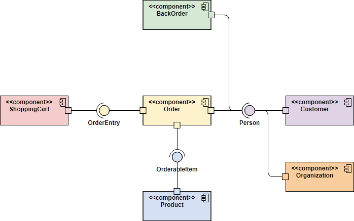
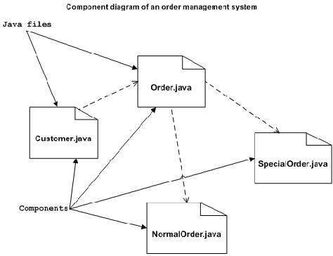
In the diagram below each component is enclosed in a small box. ________ relationship between use cases means that the base use case explicitly incorporates the behavior of another use case at a location specified in the base. Just like a relation a function is also a set of ordered pairs.
UML object naming syntax - objectName. In the first version of UML components included in these diagrams were. This question has 3 correct answers.
Q009 This diagram shows how the tilt of a magnetic needle changes with latitude. A UML deployment diagram is a diagram that shows the configuration of run time processing nodes and the components that live on them. Deployment diagrams is a kind of structure diagram used in modeling the physical aspects of an object-oriented system.
This type of diagrams is used in Component-Based Development CBD to describe systems with Service-Oriented Architecture SOA. E-R case diagram AnswerB. On the other hand a function is actually a special kind of relation because it follows an extra rule.
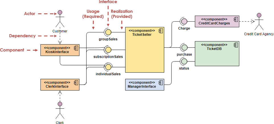
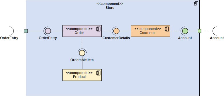
Getters and setters operations should not be shown in a class diagram. Component diagrams are often drawn to help model implementation details and double-check that every aspect of the systems required functions is covered by planned development. A component diagram also known as a UML component diagram describes the organization and wiring of the physical components in a system.
An entity is represented as rectangle in an ER diagram. Collaboration Diagrams are preferred because the layout indicates how objects are statically connected. In the following ER diagram we have two entities Student and College and these two entities have many to one relationship as many students study in a single college.
A systems integrator is a special kind of consultant who has expertise in making the different hardware and software components of an information system work together. Lines of magnetic force Click to view larger image Select one. A diagram that shows the overall structure of a system as it exists after it is deployed is called what.
Use case diagram C. Suppose we have two relations written in tables A relation that is not a function. Component serves as a type whose conformance is defined by.
Graphically a component diagram is a collection of vertices and arcs and commonly contain components interfaces and dependency aggregation constraint generalization association and realization relationships. A component has its behavior defined in terms of provided interfaces and required interfaces potentially exposed via ports.
Component Diagram Tutorial

The Basics V2 0 Complete Lab Etron Circuit Labs Electronics Basics Electronic Engineering Electronics Projects
Component Diagram Tutorial

Use Case Templates To Instantly Create Use Case Diagrams Online Creately Blog Use Case Case Management Hospitality Management

Pin Pa Diagrams
Component Diagram Tutorial
Deployment Diagram Tutorial

Uml Class Diagram Class Diagram Diagram Class

Uml Diagram Types Learn About All 14 Types Of Uml Diagrams
Uml Component Diagrams

Component Diagram For Inventory Management System You Can Edit This Template And Create Your Own Diag Component Diagram Relationship Diagram Sequence Diagram

Component Diagram Tutorial

Uml Diagram Types Learn About All 14 Types Of Uml Diagrams
Uml Component Diagram Javatpoint
Use Case Diagram Tutorial Guide With Examples Creately Blog Use Case Check And Balance Tutorial
Deployment Diagram Tutorial
Component Diagram Tutorial

King Chess Game Design Components Diagram Component Diagram Diagram Game Design

It S A Special Kind Of Component Whose Name Has To Start With Cap And Have Open Outline Whose Opening Is The Same As Stem Width Glyphs Rectangle Rectangles


0 Comments