In Unified Modeling Language UML a component diagram depicts how components are wired together to form larger components or software systems. 7 drawing uml class diagrams.
Component Diagram Tutorial
All of the symbols shown below are found in the UML Entity Relationship and Entity Relationship shape library of Lucidchart.

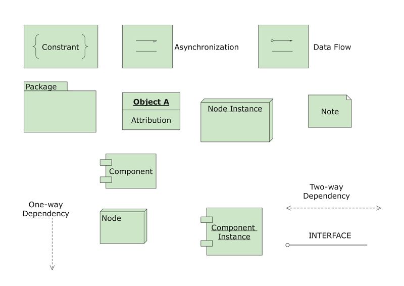
Component diagram symbols meaning. Pre-drawn UML component diagram symbols represent component package package container dependency generalization tranparent stereotype opaque stereotype and note etc. Lamp Light Bulb Symbols. Visualizing each element in the process makes it easy to identify inefficiencies and.
They may also be used to form commonality relationships between ER models as a basis for data model integration. In order to represent the various components used in the diagram electrical symbols are used. Deployment diagram Interaction diagrams 22.
Address the static design view of a system. In this component diagram tutorial we will look at what a component diagram is component diagram symbols and how to draw one. DFD symbols are visual representations of an organizations process or system to make it easy to understand and prune.
UML component diagram templates offer you many useful shapes. Generates light when current flows through. UML Component diagrams are used in modeling the physical aspects of object-oriented systems that are used for visualizing specifying and documenting component-based systems and also for constructing executable systems through forward and reverse engineering.
What is Component Diagram. A line diagram is used to show the relationship between circuits and their components but not the actual location of the components. Components Symbols And Notations.
Basics 10 480 V Pump Schematic. In this article we will discuss what are ER Diagram ER Diagrams Symbols Notations Their various components like Entity. Class Diagram A class diagram shows a set of classes interfaces and collaborations and their relationships.
Line diagrams provide a fast easy understanding of the connections and use of components. In UML a component diagram visually represents how the components of a software system relate to one another. Circuit diagrams provide the component layout in any circuit.
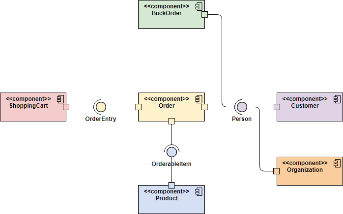
You can use a component diagram example below to get a quick start. A component diagram also known as a UML component diagram describes the organization and wiring of the physical components in a system. These symbols help create accurate diagrams and documentation.
Component diagrams are used to visualize the organization of system components and the dependency relationships between. Basics 9 416 kV Pump Schematic. E-R diagram is the short form of Entity-Relationship diagram.
15 Class Diagram Symbols Meaning. Conceptual ERDs can be used as the foundation for logical data models. Lamp light bulb.
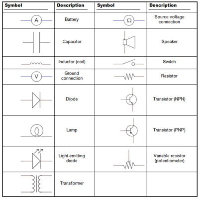
Printable Chart of Electrical Symbols with their Meanings. Component diagrams are essentially class diagrams that focus on a systems components that often used to model. Basics 11 MOV Schematic with Block included Basics 12 12-208 VAC Panel Diagram.
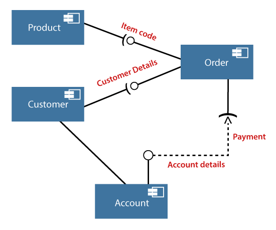
Basics 13 Valve Limit Switch Legend. These symbols represent the interfaces where a component requires information in order to perform its proper function. They are used to illustrate the structure of arbitrarily complex systems.
Object Oriented Design and Analysis 1. An e-r diagram efficiently shows the relationships between various entities stored in a database. Heres a printable electrical symbols chart for your reference when preparing circuit diagrams.
Has near zero resistance. In these diagrams the inner component depicts a minimum while the outer component depicts a maximum value. Has very high resistance.
Basics 14 AOV Schematic with Block included Basics 15 Wiring or Connection Diagram. These ER diagram symbols can be paired in different ways to depict the overall cardinality in our database. Component diagram 9.
In software engineering a class diagram in the unified modeling language uml is a type of static structure diagram that describes the structure of a system by showing the systems classes their attributes operations or methods and the relationships among objects. To build one try using Lucidcharts custom component diagram shape library. E-R Diagrams in DBMS.
Component diagrams are often drawn to help model implementation details and double-check that every aspect of the systems required functions is covered by planned development. Lamp light bulb. A line ladder diagram is a diagram that shows the logic of an electrical circuit or system using standard symbols.
Basics 8 AOV Elementary Block Diagram. What is a Component Diagram. Lamp light bulb.
The data flow diagram provides information about the process itself outputs and inputs of each entity and the various subprocesses the data moves through. Basics 7 416 kV 3-Line Diagram. Most common diagram found in modeling object- oriented systems.
Uml Component Diagram Javatpoint
Component Diagram Tutorial

Uml Diagram Types Learn About All 14 Types Of Uml Diagrams
Vhhrwchbkccmom

Design Elements Uml Class Diagrams Uml Class Diagram Notation

Component Diagram For Inventory Management System You Can Edit This Template And Create Your Own Diag Component Diagram Relationship Diagram Sequence Diagram
Circuit Symbols Of Electronic Components Electrical Electronic Symbol


What Is Deployment Diagram Archimetric

Schematic Symbols Electrical Symbols Electrical Schematic Symbols Circuit Diagram
Component Diagram Tutorial Lucidchart

Uml Diagram Types Learn About All 14 Types Of Uml Diagrams
Electronics Schematics Commonly Used Symbols And Labels Dummies

Skill Set Reading Circuit Diagrams Make Diy Projects And Ideas For Makers Circuit Diagram Electrical Circuit Symbols Electrical Symbols

Deployment Diagram Everything That You Need To Know My Chart Guide

Uml Component Diagram Component Diagram Diagram Diagram Design

Schematic Symbols Electronics Circuit Electrical Circuit Diagram Electrical Symbols

Component Diagram An Overview Sciencedirect Topics

Uml Component Diagram Component Diagram Diagram Diagram Design

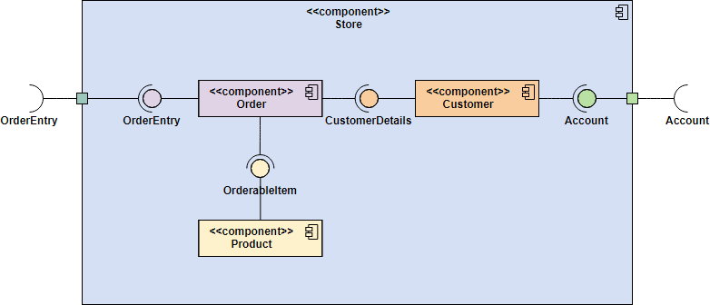
Free Editable Online Store Process Uml Component Diagram Edrawmax In 2021 Component Diagram Time Diagram Diagram


0 Comments