EJB is an essential part of a J2EE platform. Cloud computing architecture is divided into the.
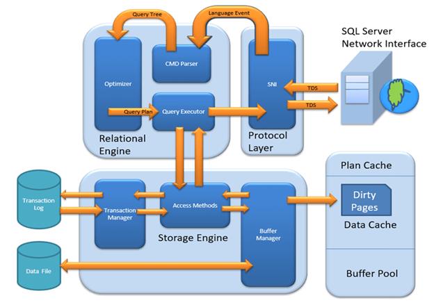
Sql Server Architecture Diagram
The weak entity is the entity that depends on the existence of another entity.

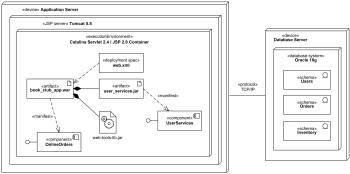
Component diagram guru99. A component diagram breaks down the actual system under development into various high levels of functionality. Partition 1 has two offset factors 0 and 1. Object diagram class diagram individual objects heap layout objectName.
With CBD the focus shifts from software programming to software system composing. Cloud computing architecture is a combination of service-oriented architecture and event-driven architecture. Type attribute value lines show field references Class diagram.
EJB provides an architecture to develop and deploy component based enterprise applications. An entity is a person place or event relevant to the given system. Component of ER Diagram 1.
Component-based development CBD is a procedure that accentuates the design and development of computer-based systems with the help of reusable software components. This free UML tutorial covers topics like Use Cases Object Diagrams Component Diagrams State Diagrams Activity Diagrams etc. The following diagram illustrates the main terminologies and the table describes the diagram components in detail.
41 Use a Professional ER Diagram Tool. Though to make the most of these symbols and get better results with your Entity-relationship Diagrams consider the following tips. 12 Components Of A Class Diagram.
As we know cloud computing technology is used by both small and large organizations to store the information in cloud and access it from anywhere at anytime using the internet connection. Free Catalogs Show details. This Online UML Course is a step by step guide to learn UML.
Partition 2 has four offset factors 0 1. Simply launch the smartdraw class diagram extension and point it to github or a local directory choose which classes you want to include and. Class diagram Object diagram Component Diagram Deployment diagram.
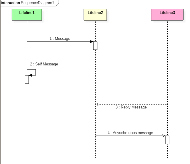
These are mostly used when working with complex. Just Now UML Course Summary. The collaboration diagram is used to show the relationship between the objects in a system.
A database diagram is composed of different parts and 3 essential elements are. Dynamic Diagrams Also called Behavioral Diagrams. J2EE platform has component based architecture to provide multi-tiered distributed and highly transactional features to enterprise level applications.
Each component is responsible for one clear aim within the entire system and only interacts with other essential elements on a need-to-know basis. In the ER diagram an entity can be represented as rectangles. The main components of E-R model are.
File system management 4. Instead of showing the flow of messages it depicts the architecture of the object residing in the system as it is based on object. Both the sequence and the collaboration diagrams represent the same information but differently.
UML Diagram Tutorial for Beginners. Consider an organization as an example- manager product employee department etc. Entity set and relationship set.
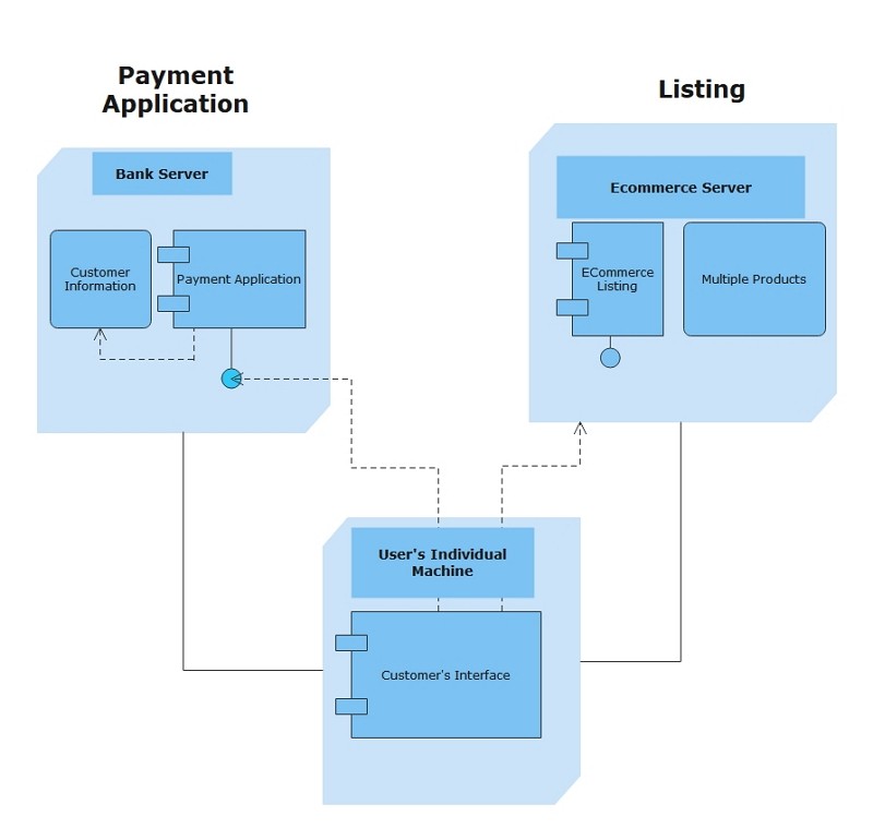
Component diagrams Deployment diagrams. The data account. EJB stands for Enterprise Java Beans.
For each task you will include a Venn diagram and approximately two paragraphs of explanation. An entity may be any object class person or place. The following diagrams are dynamic diagrams.
In other words ER diagrams help to explain the logical structure of databases. An entity that depends on another entity called a weak entity. The nine diagrams are divided into static diagrams and dynamic diagrams.
Component-based development techniques involve procedures for developing software systems by. 2 days ago Aug 28 2021 UML stands for Unified Modeling Language. Expert Tips for Using ER Diagram Symbols As you can see there are so many different ER diagram symbols that you can use to create various diagrams.
The example above shows the internal components of a larger component. Can be taken as an entity. Sep 21 2021 Your Venn diagrams should illustrate the five tasks that OSs perform which are listed below.
In the above diagram a topic is configured into three partitions. Class diagrams model the static structure of a system. ER diagrams are created based on three basic concepts.
Static Diagrams Also called Structural Diagram. ER Diagram stands for Entity Relationship Diagram also known as ERD is a diagram that displays the relationship of entity sets stored in a database. It is a standard which is mainly used for creating object-oriented meaningful documentation models for any software system present in the real world.
The following diagrams are static diagrams. An Entityrelationship model ER model describes the structure of a database with the help of a diagram which is known as Entity Relationship Diagram ER DiagramAn ER model is a design or blueprint of a database that can later be implemented as a database. Planning and modeling ahead of time make programming much easier.
Entities attributes and relationships. Very big but a nice standard that has been embraced by the industry. Device management and 5.

Uml Diagram Cheat Sheet And Reference Guide
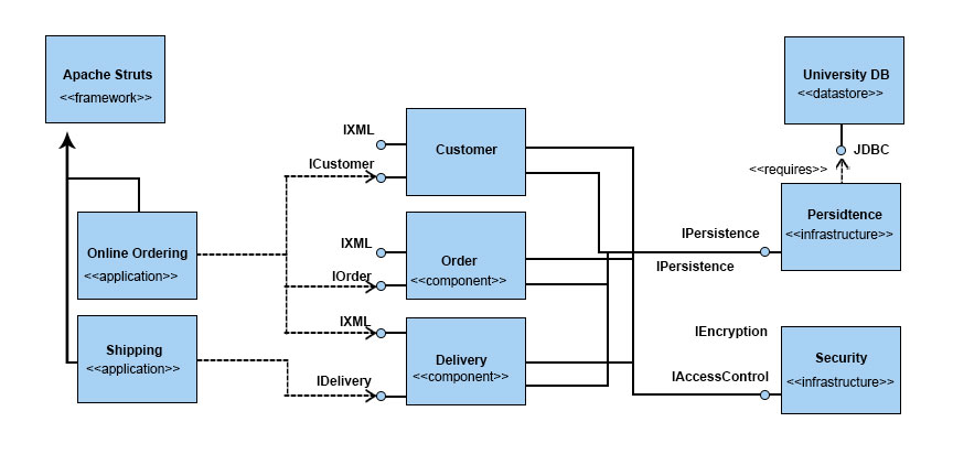
Uml Component Diagram Example Code
2

What Is Data Warehousing Types Definition Example Https Www Guru99 Com Data Warehousing Html What Is Data Data Data Warehouse

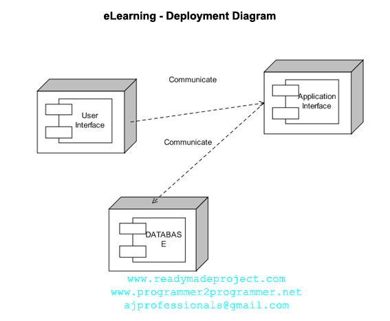
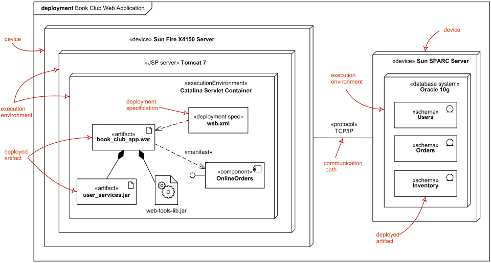
Deployment Diagram Tutorial Lucidchart
Deployment Diagram Online

Deployment Diagram Online

Uml Diagram Cheat Sheet And Reference Guide

Deployment Diagram Online
Deployment Diagram Online

Data Warehouse Architecture Concepts And Components

Uml Diagram Cheat Sheet And Reference Guide

A Brief Look Into How Code And Binary By Jon Sy Chan Medium
Class Diagram For Angular Application

Data Warehouse Architecture Concepts And Components
Uml Diagram Cheat Sheet And Reference Guide
Deployment Diagram Online
Deployment Diagram Online

Hadoop Comes With A Distributed File System Called Hdfs Hadoop Reading Writing Reading Writing


0 Comments