The main feature of a control system is that there should be a clear mathematical relationship between the input and output of the system. 11 Draw a component block diagram for each of the following feedback control systems.

Block Diagram Of Control Systems Transfer Functions Reduction Summing Points Electrical4u
History of Feedback Control 11 Problems and Solutions 1.

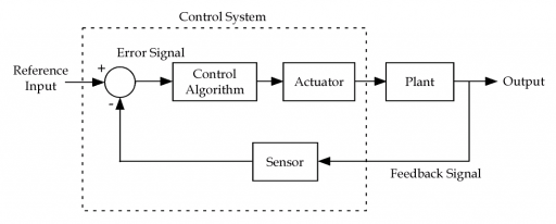
Draw a component block diagram for each of the following feedback control systems. Typically a block diagram will be developed for a system. The major concerning factors of a feedback system include sensing controlling and actuating the process inside the system. A control system is an interconnection of components forming a system.
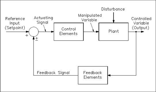
Block diagrams consist of Blocksthese represent subsystems typically modeled by and labeled with a transfer function Signals. The diagram will then be simplified through a process that is. Feedback control in block diagram for a cruise control system.
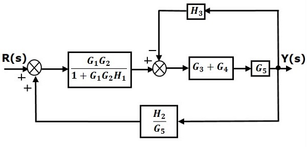
The block diagram of Figure 3-44 can be modified to that shown in Figure 3-45a. Draw a component block diagram for each of the following feedback control system. Figure 3-46 Block diagram of a system.
Problem 101PP Draw a component block diagram for each of the following feedback control systems a The manual steering system of an automobile b Drebbels incubator c The water level controlled by a float and valve d Watts steam engine with fly-bail governor In each case indicate the location of the elements listed below and give the units associated with each signal. Feedback control - 87 832 Manipulating Block Diagrams A block diagram for a system is not unique meaning that it may be manipulated into new forms. At the summing point the input signal R s will be added to B s.
2 Closed loop feedback control systems r r s e e t l l g l u k u a ct 1 t - Features. The manual steering system of an automobile b. Block diagram shown in Figure 3-44.
A The manual steering system of an automobile b Drebbels incubator c The water level controlled by. The modified block diagram is shown in the following figure. Draw a component block diagram for each of the following feedback control systems a The manual steering system of an automobile b Drebbels incubator c The water level controlled by a float and valve d Watts steam engine with fly-bail governor.
Step 6 Use Rule 3 for blocks connected in feedback loop. A The manual steering system of an automobile b Drebbels incubator c The water level controlled by a float and valve d Watts steam engine with fly-ball governor. Following the functional block diagram from task 1 we now want to create a pantograph active-control loop by adding the following components.
A system or element whose transfer function is Gs may be represented by a block diagram as shown in the figure. Problems 11 cd 12 16ah 11 Draw a component block diagram for each of the following feedback control systems. You can learn more about control systems by studying our control system MCQs.
A The manual steering system of an automobile b Drebbels incubator c The water level controlled by a oat and valve. Step 5 Use Rule 1 for blocks connected in series. The modified block diagram is shown in the following figure.
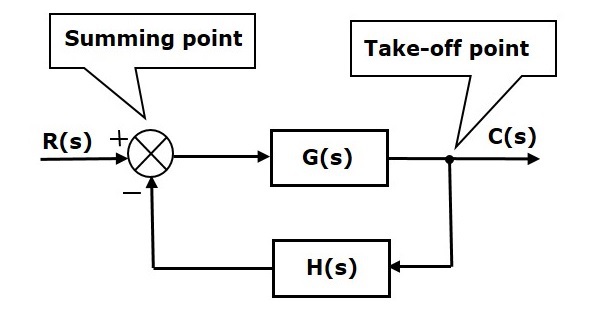
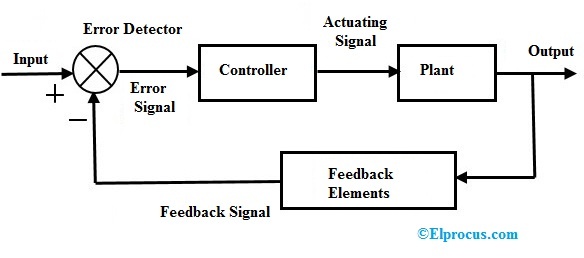
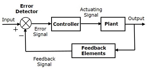
Basic Elements of Block Diagram. Get the Simulink block diagram for figure 3b from model equations. Let us consider the block diagram of a closed loop control system as shown in the following figure to identify these elements.
The principles of control theory are applicable to both engineering and non-engineering field. Feedback Control System Advantages and Disadvantages. Draw a component block diagram for each of the following feedback control systems.
The modified block diagram is shown in the following figure. The basic elements of a block diagram are a block the summing point and the take-off point. Block Diagram of Closed Loop Control System.
Input transducer G i s 001 controller G c s K actuator G a s 0001 pantograph spring K s 823 x 103. The following table shows the control system design process. In a block diagram all system variables are linked to each other through functional block the functional block is a symbol for the mathematical operation on the input signal to the block that produces the output.
Webb MAE 4421 3 Block Diagrams In the introductory section we saw examples of block diagrams to represent systems eg. Not only there is a forward action also a backward action between the output and the input measuring the output and comparing it with the input. You May Also Read.
Features of a Control System. What is Block Diagram A bock diagram is pictorial representation of the functions performed by each component and of the flow signals. Find applications of the feedback systems.
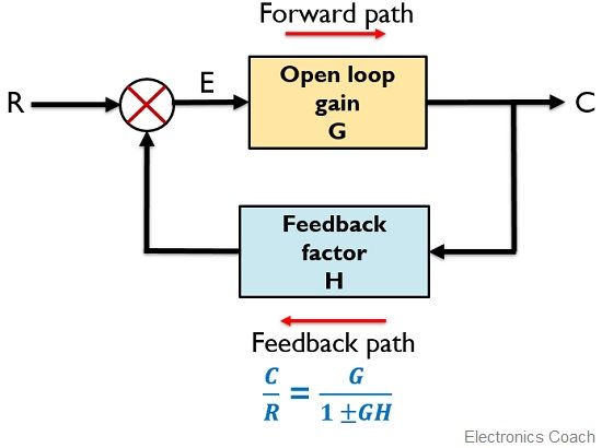
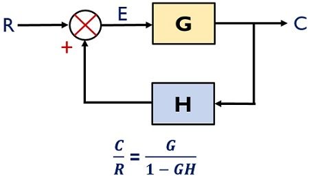
Problem 101PP Draw a component block diagram for each of the following feedback control systems a The manual steering system of an automobile b Drebbels incubator c The water level controlled by a float and valve d Watts steam engine with fly-bail governor In each case indicate the location of the elements listed below and give the units associated. Majorly electronics circuits like amplifiers oscillators etc. The figure here shows the block diagram of the control system with feedback.
Block Diagram of Feedback System. A The manual steering system of an automobile b Drebbels incubator c The water level controlled by a float and valve d Watts steam engine with fly-ball governor In each case indicate the location of the elements listed below and give the units. In a closed-loop control system a fraction of output is fed-back and added to the systems input.
The water level controlled by a float and valve d. Draw a component block diagram for each of the following feedback control systems. Draw a component block diagram for each of the following feedback control system.
1k Electric motor Valve k Shaft speed meter Desired Shaft speed. Eliminating the minor feedforward path we obtain Figure 3-45b which can be simplified to that shown in Figure 3--5cThe transfer function CsRs is thus given by. Watts steam engine with fly-ball governor In each case indicate the location of the elements listed below and.
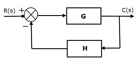
If H s is the transfer function of the feedback path then the transfer function of the feedback signal will be B s C sH s. This is the simplified block diagram. A The manual steering system of an automobile b Drebbels incubator c The water level controlled by a float and valve d Watts steam engine with fly-ball governor In each case indicate the location of the elements.
1 measuring the output controlled variable. The above block diagram consists of two blocks having transfer functions Gs and Hs. When the relation between input and output.
Block diagram of transfer function Gs If the transfer function is a constant K the diagram in the following figure is used.
Control System Basics Ledin Engineering Inc

Temperature Controller Basics Handbook Instrumart
Control Systems Block Diagrams
What Is Feedback System Block Diagram And Types Of Feedback Electronics Coach
The Basics Of Process Control Diagrams Technology Transfer Services
Wescott Design Services Using Block Diagrams

7 General Block Diagram Of Control Loops A Open Loop And B Closed Download Scientific Diagram
Control Systems Block Diagram Reduction

Feedback Systems And Feedback Control Systems
Control System Principles Tikz Example

Feedback Systems And Feedback Control Systems
![]()
Block Diagram Algebra Objective Questions Inst Tools
Closed Loop Control System Block Diagram Types Its Applications
What Is Feedback System Block Diagram And Types Of Feedback Electronics Coach
Control Systems Feedback

Block Diagram Of Cnc Machine Tool Control System Download Scientific Diagram
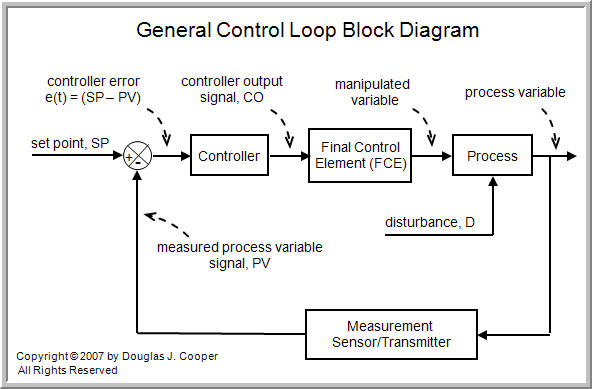
The Components Of A Control Loop Control Guru
Control Systems Quick Guide
2


0 Comments