This type of diagrams is used in Component-Based Development CBD to describe systems with Service-Oriented Architecture SOA. These are the shapes you draw to represent the components or building blocks of the system you are describing.
Component Diagram Tutorial
Graphically a component diagram is a collection of vertices and arcs and commonly contain components interfaces and dependency aggregation constraint generalization association and realization relationships.

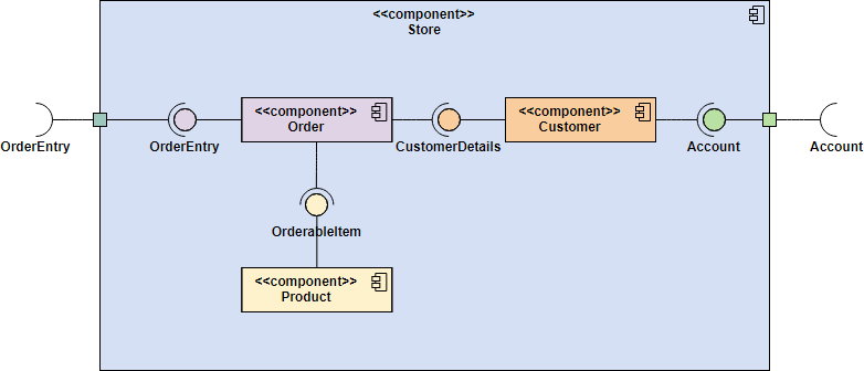
Component diagram relationships. The behavior is defined in terms of required and provided interfaces. You can create a UML component diagram to show components ports interfaces and the relationships between them. One way of illustrating the provided and required interfaces by the specified component is in the form of a rectangular.
Component diagram shows components provided and required interfaces ports and relationships between them. The component diagram extends the information given in a component notation element. Component diagrams are often drawn to help model implementation details and double-check that every aspect of the systems required functions is covered by planned development.
In UML a relationship is a connection between model elements. Relationships in component diagrams. An entity relationship diagram ERD shows the relationships of entity sets stored in a database.
A UML relationship is a type of model element that adds semantics to a model by defining the structure and behavior between model elements. A component in UML represents a modular part of a system. A is the collection class source and B is the member class destination.
For the purpose of UML 20 the term component refers to a module of classes that represent independent systems or subsystems with the. You can use realization relationships in class diagrams and component diagrams. A Component diagram has a higher level of abstraction than a Class diagram.
Component diagrams illustrate the pieces of software embedded controllers etc that will make up a system. A component has an external view with public properties and operations and it has an internal view with private properties. They provide a high-level view of the components within a system.
An Entity-relationship model A diagram is used to describe the structure of a database. A Component diagram illustrates the pieces of software embedded controllers and such that make up a system and their organization and dependencies. A component in UML represents a modular part of a system.
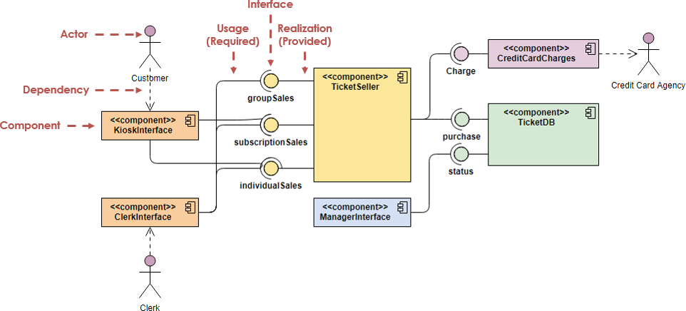
These entities can have attributes that define its properties. E-R models are composed of two main components of ER Diagram. Usage relationships In UML modeling a usage relationship is a type of dependency relationship in which one model element the client requires another model element the supplier for full implementation or operation.
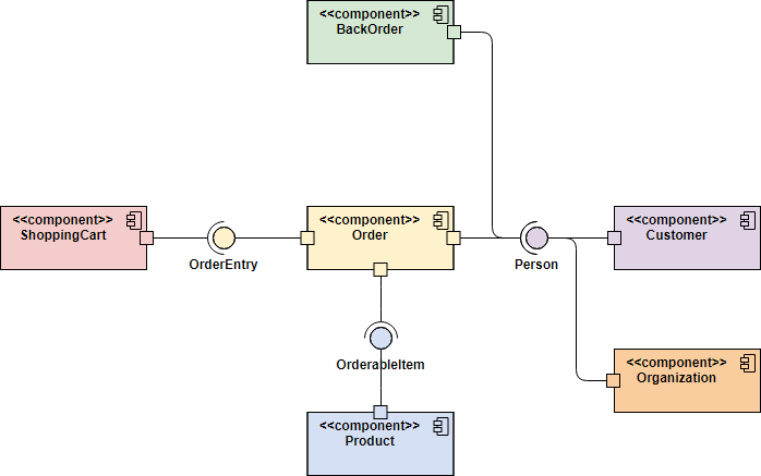
The purpose of a component diagram is to show the relationship between different components in a system. A component has an external view with public properties and operations and it has an internal view with private properties. They are building blocks so a component can eventually encompass a.
Component-based development is based on assumptions that previously constructed. It illustrates the architectures of the software components and the dependencies between them. This is also known as Entity Relationship Diagram ER Diagram.
Those software components including run-time components executable components also the source code components. Usually a component is implemented by one or more Classes or Objects at runtime. An ER model can be described as a blueprint or design for a database that can later become a database.
A component diagram has a higher level of abstraction than a Class Diagram - usually a component is implemented by one or more classes or objects at runtime. In the first version of UML components included. An entity in this context is an object a component of data.
Relationships add information to your diagram by clarifying the way that elements interact or. The Component Diagram helps to model the physical aspect of an Object-Oriented software system. They provide a high-level view of the components within a system.
An entity set is a collection of similar entities. A component diagram also known as a UML component diagram describes the organization and wiring of the physical components in a system. Relationships are also a type of model element.
UML component diagrams show the relationships between individual system components through a static conceptual visualization. You can create a UML component diagram to show components ports interfaces and the relationships between them. The collection class uses properties of the member class.
In UML components are modular parts of a system that are independent and can be replaced with equivalent componentsThey are self-contained and encapsulate. Both logical and physical modelling aspects can be included. In the following diagram BMC_MemberOfCollection relationship is represented by black lines.
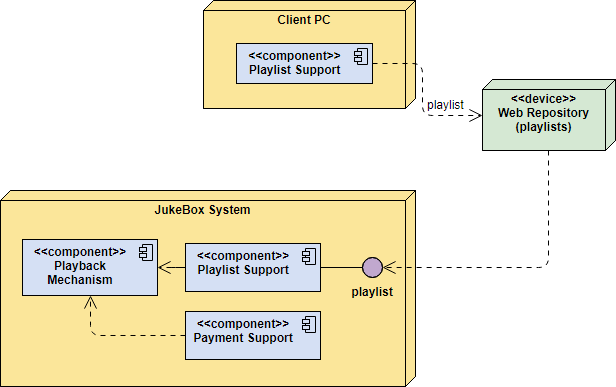
The behavior is defined in terms of required and provided interfaces. Component relationships are represented by green lines. A port is often used to help expose required and provided interfaces of a component.
System administrators can use component diagrams to plan ahead using the view of the logical software components and their relationships on the system. Component diagrams are used to visualize the organization of system components and the dependency relationships between them.

Component Diagram Tutorial Lucidchart

Component Diagram Tutorial Lucidchart

Uml Component Diagram Component Diagram Diagram Diagram Design
Component Diagram Tutorial

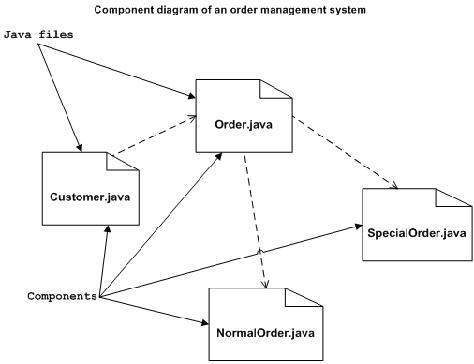
A Uml Component Diagram For The Order Processing Example Download Scientific Diagram

Uml Diagram Types Learn About All 14 Types Of Uml Diagrams

Uml Component Diagram Component Diagram Diagram Diagram Design
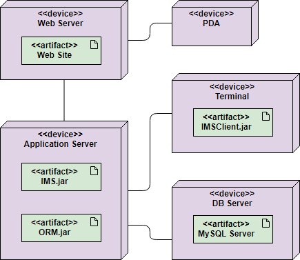
Deployment Diagram Tutorial

Component Diagram An Overview Sciencedirect Topics
Component Diagram Tutorial
Component Diagram Tutorial

Component Diagram Tutorial Lucidchart

Component Diagram Component Diagram Diagram Process Flow Diagram
Demo Start Component Diagram Complex Systems Diagram
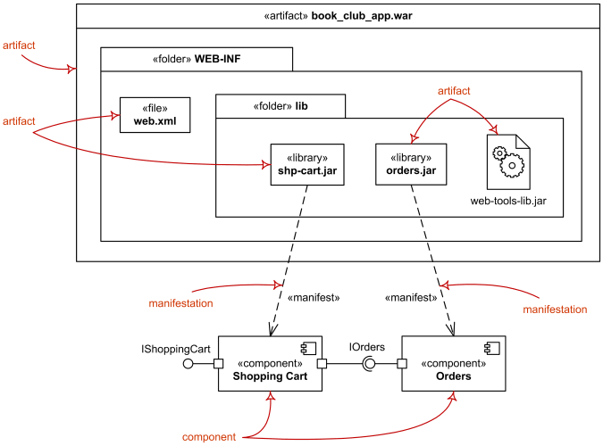
Uml Deployment Diagrams Overview Common Types Of Deployment Diagrams Manifestation Diagram Specification And Instance Level Deployment Diagram

This Component Diagram Shows The Relationship Between Different Components In A System Component Diagram Helps You In Man Component Diagram Diagram Components

Uml Diagram Types Learn About All 14 Types Of Uml Diagrams
Uml Component Diagrams

Component Diagram Tutorial


0 Comments