When you are building a Component diagram the first step is to identify the basic components used in the system. Realizations can only be shown on class or component diagrams.

The Bartlett Book 2014 Bartlett School Of Architecture Architecture Design Process School Architecture
Lollipop 14 Component Source File Name Executable Name Component Name A component may be 1.

Component diagram lollipop. A Component UML Component Diagram represents a modular part of a system. Which is working out fine. This specific diagram does not show which class contained within the.
In a component diagram components are generic types rather than instances. A component is an autonomousunit within a system UML component diagrams enable to model the high-level software components and the interfaces to those components Important for component-based development CBD Component and subsystems can be flexibly REUSED and REPLACED UML components diagrams are Implementation diagrams ie it. The vector stencils library Bank UML component diagram contains 13 shapes for drawing UML component diagrams.
Dependencies indicate that a client component is dependent upon a supplier component in some way. It illustrates the architectures of the software components and the dependencies between them. Dependencies indicate that a client component is dependent upon a supplier component in some way.
In the diagram below each component is enclosed in a small box. A component diagram is similar to a class diagram in that it illustrates how items in a given system relate to each other but component diagrams show more complex and varied connections that most class diagrams can. This is modeled using the lollipop notation.
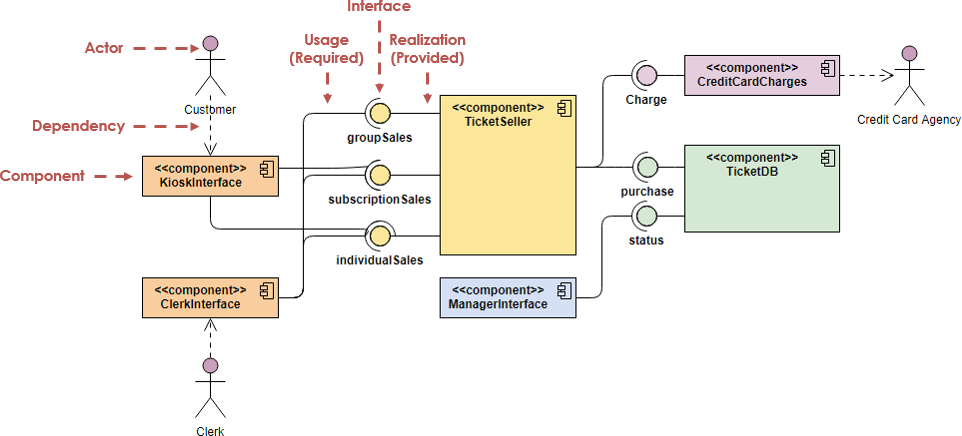
This type of diagrams is used in Component-Based Development CBD to describe systems with Service-Oriented Architecture SOA. A Required Interface of a component in a UML Component Diagram declares the services that the component expects from its environment. Examples of stereotypes in components include executables documents database tables files and library files.
A realization is a relationship between classes interfaces components and packages that connects a client element with a supplier element. Use it for object-oriented modeling of your bank information system. Under Template Categories click Software and then click UML Model Diagram and then click Create.
In a static structure component or deployment diagram drag the lollipop Interface shape represented by a line and circle onto the drawing page. A component diagram breaks down the actual system under development into various high levels of functionality. Component-based development is based on assumptions that previously constructed components could be reused and that components could be.
So I can show that the Array class implements multiple interfaces like this. Add an interface to a class component or other element. Double-click the Interface shape to add a name operations and other property values.
These used to be shown as components but are now documented as artifacts. On a component diagram with lollipops and sockets note that the dependency arrow comes out of the consuming requiring socket and its arrow head connects with the providers lollipop as shown in Figure 5. A run time component or 3.
To show component instances use a deployment diagram. Why is the Word. Now when you go to your component diagram you can add your component from the component palette.
Select the Modelling UML diagrams Component branch of the tree. In all the UML 2 books that I read this can be accomplished with the lollipop on a class diagram but I was not able to find it in VP-UML. Check the Show External View on components box.
Those software components including run-time components executable components also the source code components. So Im using the component diagram as class diagrams currently. Components interact via interfaces shown here using the lollipop notation.
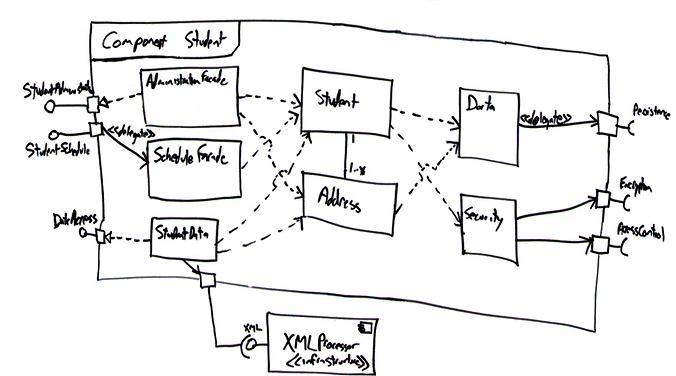
Under Template Categories click Software and then click UML Model Diagram and then click Create. This is modeled using the lollipop notation. The example above shows the internal components of a larger component.
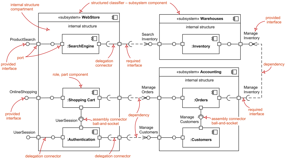
Component diagram shows components provided and required interfaces ports and relationships between them. In component diagrams the ball-and-socket graphic convention is used implementors expose a ball or lollipop whereas users show a socket. To show component instances use a deployment diagram.
Glue the endpoint without the circle to a connection point on the class component or other element. Component Diagram Deployment Diagram. The origins of this was the lollipop notation that was popularized by Microsoft to show a class implementing multiple interfaces.
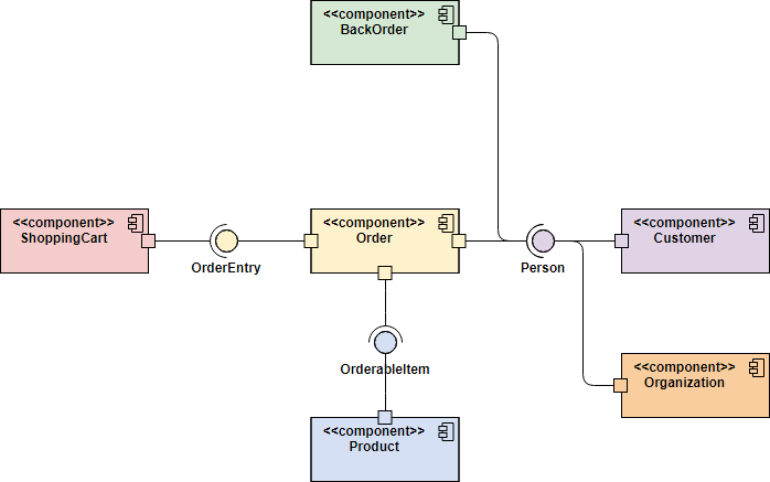
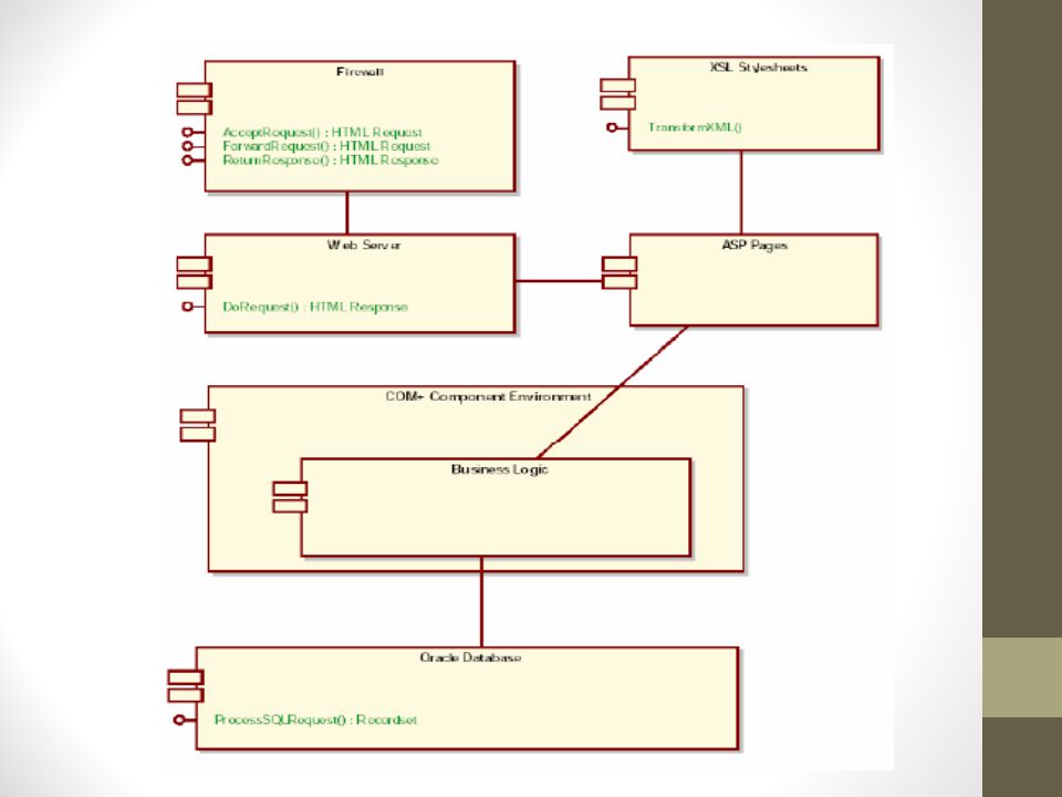
The Component Diagram helps to model the physical aspect of an Object-Oriented software system. Component diagram for an ATM system. A component diagram that shows how the Order System component depends on other components.
This is modeled using the socket notation. The lollipop indicates the interface between the component and its clients. A Provided Interface of a component in a UML Component Diagram describes the services that the component offers to its environment.
This component provides interface I1 meaning it outputs information in the form of I1 and requires interface I2 meaning it requires input in the form of I2. UML Component Diagrams R R R Implementation Diagrams. The data account.
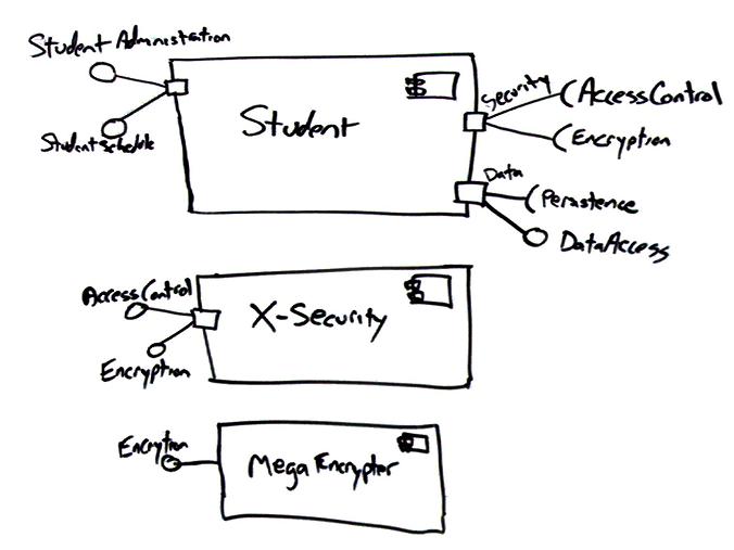
However I found the lollipop notation available in the component diagram. Avoid Modeling Data and User Interface Components Interfaces Prefer Lollipop Notation To Indicate Realization of Interfaces B y Components Prefer the Left-Hand Side of A Component for Interface Lollipops. A source code component 2.
This kind of interface is represented by a solid line with a lollipop. Each component is responsible for one clear aim within the entire system and only interacts with other essential elements on a need-to-know basis. The above diagram treats each source object and executable file as a separate component.
In a component diagram components are generic types rather than instances. One of the new notations that appeared in UML 2 was the socket notation to show interfaces required by a class. A component is something required to execute a stereotype function.
In any real project there will be hundreds of files involved.

Abc Of Pon Understanding Olt Onu Ont And Odn Fiber Optic Voip Network Switch

Skema Antena Tv Yang Bagus In 2021 Tv Yang

Emmc Isp Pinout V1 0 Latest All Pinout 2020 Oppo Vivo Realmexiaomi Free Download Emmc Isp Pinout V1 0 Feature Vivoemmc Isp Pinouttool Opp Isp Xiaomi Vivo

Component Diagram Ppt Download

Could Plantuml Support O And O Arrow Notations For Component Diagrams Plantuml Q A
Component Diagram Tutorial
Uml 2 Component Diagramming Guidelines

Introduction To Uml 2 Component Diagrams
Component Diagram Tutorial
Introduction To Uml 2 Component Diagrams
Uml Component Diagram Reference Components Provided And Required Interfaces Ports Relationships Between Them Etc

Understanding Dependency Relationship In Uml Component Diagram Stack Overflow
Pin De Roger Chidiac Em Electronics Esquemas Eletronicos Diagrama De Circuito Circuito Eletronico
Component Diagram Ppt Download

Component Diagram Tutorial Lucidchart

How A Dry Cell Battery Works Dry Cell Electrical Engineering Books Zinc
Introduction To Uml 2 Component Diagrams

Introduction To Uml 2 Component Diagrams


Pin By Fatemeh On Healthly Electronic Components Electronic Products Pictures


0 Comments