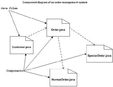
A computer system is a combination of three components. The component diagrams are for representing interfaces and dependencies among software architecture.

Component Diagram Tutorial Lucidchart
Entity set and relationship set.
Component diagram gfg. UML Component diagrams are used in modeling the physical aspects of object-oriented systems that are used for visualizing specifying and documenting component-based systems and also for constructing executable systems through forward and reverse engineering. An Entity is an object of Entity Type and set of all entities is called as entity set. It is the general-purpose modeling language used to visualize the system.
Component-level design also known as component-based software engineering CBSE is an approach to software development that emphasizes the concept of. 0 1 234 Explanation. Component Diagrams become essential to use when we design and build complex systems.
This type of diagrams is used in Component-Based Development CBD to describe systems with Service-Oriented Architecture SOA. Strongly connected component Tarjanss Algo Given a Directed Graph with V vertices and E edges Find the members of strongly connected components in the graph. The motherboard is the main system board for the computer and connects all of the internal hardware components.
When the component is instantiated copies of its internal parts are also instantiated. Details of how to model internal block diagrams are described in Chapter 6. Are examples of an entity.
A component diagram also known as a UML component diagram describes the organization and wiring of the physical components in a system. An internal block diagram shows how parts are connected as distinct from a block definition diagram that does not show connectors. A component diagram is similar to a class diagram in that it illustrates how items in a given system relate to each other but component diagrams show more complex and varied connections that most class diagrams can.
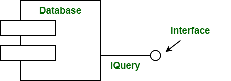
These components have ability to interface with rest of system. An entity may be an object place person or an event which stores data in the database. A component diagram shows the internal parts connectors and ports that implement a component.
The word component simply means modules of a class that usually represents an independent subsystem. Component Diagrams depict the structural relationship between software system elements and help us in understanding if functional requirements have been covered by planned development. The block diagram gives you a quick overview of the working process of a computer from inputting the data to retrieving the desired results.
Janis Osis Uldis Donins in Topological UML Modeling 2017. E1 is an entity having Entity Type Student and set of all students is called Entity Set. An Entityrelationship model ER model describes the structure of a database with the help of a diagram which is known as Entity Relationship Diagram ER DiagramAn ER model is a design or blueprint of a database that can later be implemented as a database.
It is a graphical language that is standard to the software industry for specifying visualizing constructing and documenting the artifacts of the software systems as well as for business modeling. Component diagram for an ATM system. A dependency is used to depict the relationship between dependent and independent entities in the systemAny change in the definition or structure of one element may cause changes to the other.
Order Management System UML component. This is a unidirectional kind of relationship between. Component diagrams are essentially class diagrams that focus on a systems components that often used to model the static.
In an entity-relationship diagram an entity is represented by a rectangle. 0 1 2 Explanation. In the diagram below each component is enclosed in a small box.
The main components of E-R model are. Attributes are the properties which define the entity type. Component diagrams are often drawn to help model implementation details and double-check that every aspect of the systems required functions is covered by planned development.
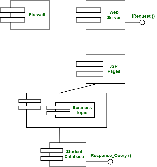
Class diagrams component diagrams deployment and object diagrams use dependency relationships. Interfaces are used by components of the system to communicate with each other. Student course manager employee patient etc.
This lesson will also look at the expansion slots used to add hardware components to a system. Unified Modeling Language UML Class Diagrams. In ER diagram Entity Type is represented as.
This lesson will take a look at various components which are built into the motherboard. The following diagram represents a block diagram of the computer system. For example Roll_No Name DOB Age.
The lesson finishes up with a discussion of the BIOS. We can clearly see that there are 3 Strongly Connected Components in the Graph as mentioned in the Output. The internal block diagram enables the modeler to specify both external and internal interfaces of a system or component.
This is a Component diagram of Order Management System which shows components provided and required interfaces ports and relationships between the Confirm Order Delivery Customer Product Quality and Product. The component diagram is used to explain working and behavior of various. An ER Diagram consists of the following components.
The UML component diagram shows how a software system will be composed of a set of deployable componentsdynamic-link.
Class Diagram Tutorial

Unified Modeling Language Uml Activity Diagrams Geeksforgeeks
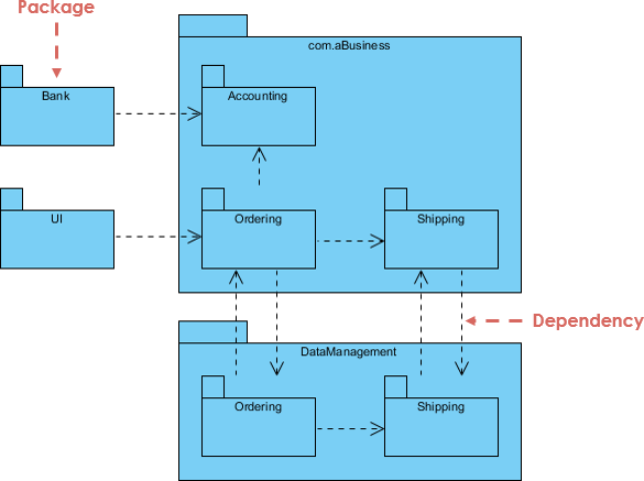
Uml What Is Package Diagram How To Use It By Warren Lynch Medium

Library Management System Collaboration Diagram Diagram State Diagram Library

Library Management System Collaboration Diagram Diagram State Diagram Library

Greece Is A Developed Country With An Economy Based On The Service 80 And Industrial Sectors 16 With The Ag Greece Agricultural Sector Developing Country

Component Diagram Tutorial Lucidchart

Shopping Center Elevation Section And Plan Details Dwg File Parking Design Shopping Center How To Plan
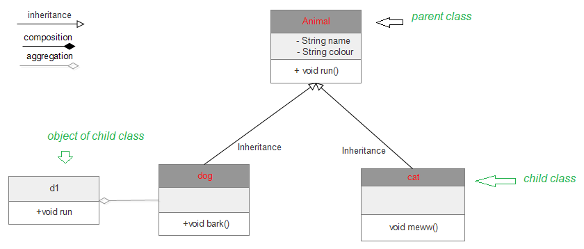
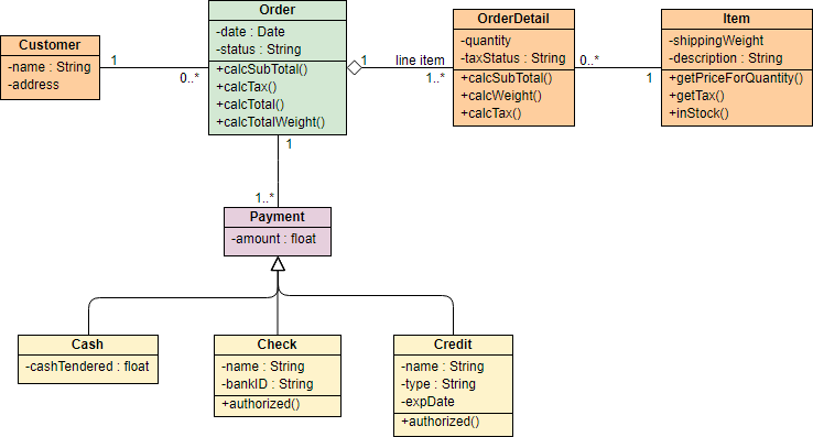
Unified Modeling Language Uml Class Diagrams Geeksforgeeks
Uml Component Diagrams

Component Diagram Tutorial Lucidchart
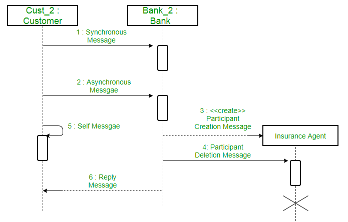
Difference Between Sequence Diagram And Activity Diagram Geeksforgeeks
Unified Modeling Language Uml Sequence Diagrams Geeksforgeeks

Uml Diagram Types Learn About All 14 Types Of Uml Diagrams Component Diagram Diagram Tutorial
Component Based Diagram Geeksforgeeks
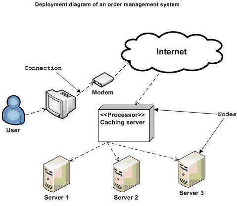
Uml Deployment Diagrams
Component Based Diagram Geeksforgeeks

Pin On Sultan

Uml Class Diagram For Online Food Ordering System You Can Modify This According To The System Structure Of Y Class Diagram Component Diagram Data Flow Diagram


0 Comments