Deployment diagram digunakan untuk memvisualisasikan menspesifikasikan dan mendokumentasikan proses yang terjadi pada suatu sistem perangkat lunak berbasis Object Oriented yang akan dibangun. Komponen diagram UML memungkinkan untuk memodelkan komponen perangkat lunak tingkat tinggi dan interface untuk.
Apa Itu Uml Beserta Pengertian Dan Contohnya Dicoding Blog
Component diagrams are essentially class diagrams that focus on a systems components that often used to model the static.
Component diagram dan deployment diagram object oriented design. - Selection from Applying UML and Patterns. Mendeskripsikan komponen software dan kebergantungannya dengan yang lain. Component diagrams and deployment diagrams.
Object-Oriented Analysis and Design Author. Deployment diagram yaitu salah satu diagram pada UML yang menunjukan tata letak suatu system secara fisik dapat juga dikatakan untuk menampilkan bagian-bagian softwere yang. Design activities concerning the overall system design specify the overall system architecture logically using a layered model and physically using component and deployment diagrams.
Object Diagram set of objects class instances and their relationships Component Diagram logical groupings of elements and their relationships Deployment Diagram - set of computational resources nodes that host each component. Contoh dari deployment diagram. Component Diagram and Deployment Diagram.
Browse Library Object-Oriented Analysis Design and Programming with UML Video. Deployment diagrams is a kind of structure diagram used in modeling the physical aspects of an object-oriented system. This is discussed in Chapter 9.
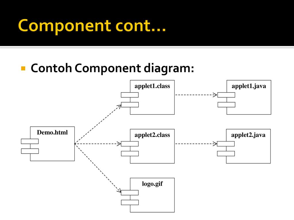
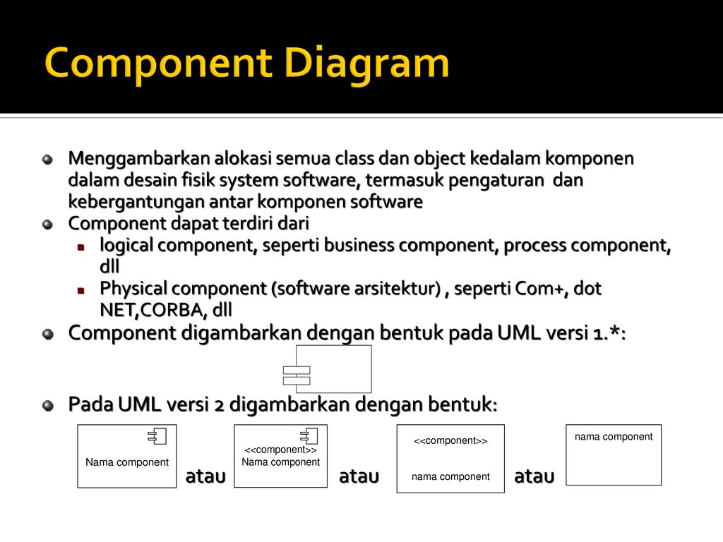
A component diagram represents the actual physical software components and their dependencies. They are often be used to model the static deployment view of a system topology of the hardware. Component diagram merupakan penerapan softwere dari satu ataupun lebih class dan biasanya berupa file data atau exe source kode table dokumen dsb.
Use-case class object state sequence collaboration activity component dan deployment diagram. Simple program design. Komponen merupakan unit otonom dalam sistem.
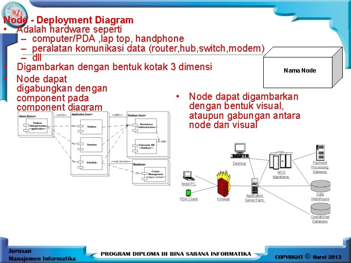
UML Deployment and Component Diagrams Call me paranoid but finding inside this comment makes me suspicious. Deployment Diagram Deploymentphysical diagram menggambarkan detail bagaimana komponen di-deploy dalam infrastruktur sistem di mana komponen akan terletak pada mesin server atau piranti keras apa bagaimana kemampuan jaringan pada lokasi tersebut spesifikasi server dan hal-hal lain yang bersifat fisikal. Component diagrams Diagram komponen.
Deployment Diagram Deploymentphysical diagram menggambarkan detail bagaimana komponen di-deploy dalam infrastruktur sistem di mana komponen akan terletak pada mesin server atau piranti keras apa bagaimana kemampuan jaringan pada lokasi tersebut spesifikasi server dan. A UML deployment diagram is a diagram that shows the configuration of run time processing nodes and the components that live on them. Mengkomunikasikan requirement kepada tim teknis karena diagram ini dapat lebih mudah untuk dielaborasi menjadi model design.
Systems Analysis and Design. A student Guide to Object Oriented Development. What is Deployment Diagram.
UML Static diagrams - UML Static diagrams Component Diagram Captures the physical structure of the implementation. Main concepts sebagai term yang akan muncul pada saat membuat diagram dan view adalah kategori dari diagram tersebut. Shape near the two classifier role or multi object shapes you want to create a path between component diagram diagram ini menggambarkan kumpulan komponen dan hubungan antar komponen collaboration diagram uml system analyst bluetooth 4 1 object oriented analysis object oriented design unified modeling language share on facebook share on.
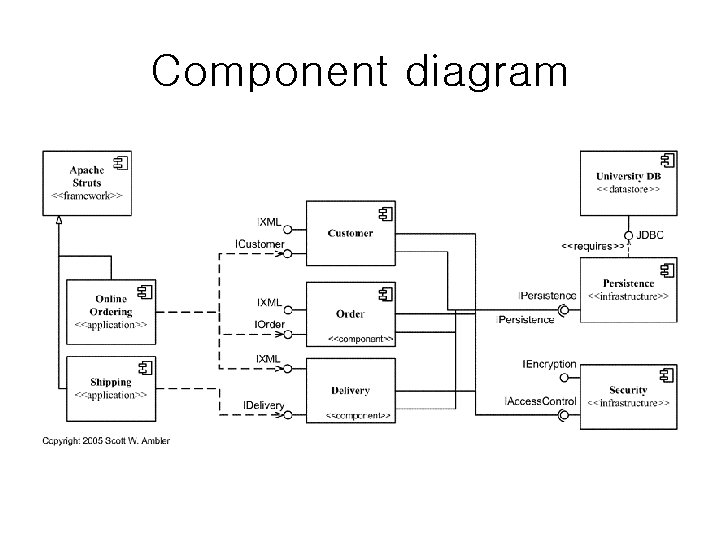
Tujuan penggunaan sequence diagram. Merupakan diagram yang paling cocok untuk mengembangkan model deskripsi use-case menjadi spesifikasi design. UML Component diagrams are used in modeling the physical aspects of object-oriented systems that are used for visualizing specifying and documenting component-based systems and also for constructing executable systems through forward and reverse engineering.
UML sendiri terdiri atas pengelompokkan diagram-diagram sistem menurut aspek atau sudut pandang tertentu. This is the first part of the two-part video that explains how to represent the physical entities of your software and hardware through a deployment diagram. UML mendefinisikan diagram-diagram sebagai Use case diagram Class diagram Statechart diagram Activity diagramSequence diagram Collaboration diagram Component diagram dan Deployment diagram Adi 2010.
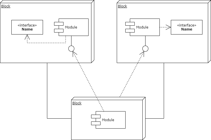
Sebuah komponent berisi informasi tentang logic class atau class yang diimplementasikan sehingga membuat pemetaan dari logical view ke component view. While other UML diagrams which describe the functionality of a system component diagrams are used to model the components that help make those functionalities. Component diagram yaitu salah satu jenis diagram pada UML yang menggambarkan softwere pada suatu sistem.
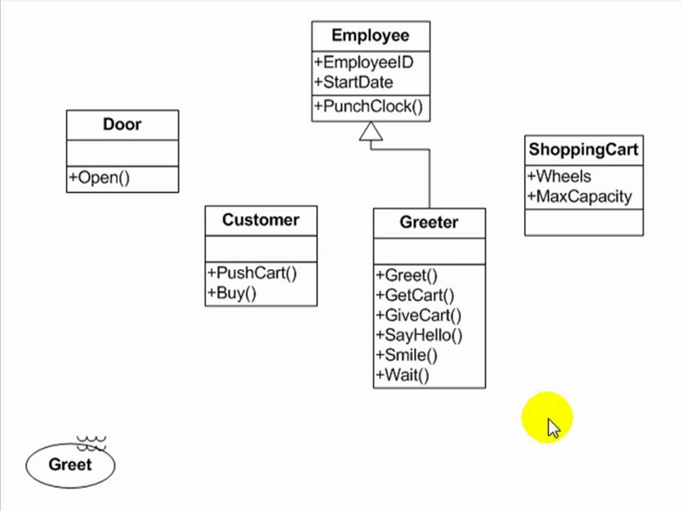
Detailed design activities in an object-oriented system require us to specify the class diagram. Waktu Penggunaan sequence diagram. The components of a system often correspond to packages but this is not necessarily the case as components represent physical software files and the packages identified in design are logical units.
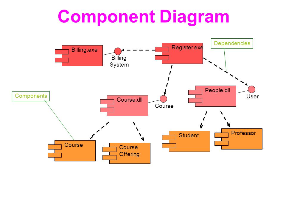
Ø Component Diagram Menggambarkan struktur fisik kode dari komponent. Siam2dev Created Date. Diagram adalah yang menggambarkan permasalahan maupun solusi dari permasalahan suatu model.
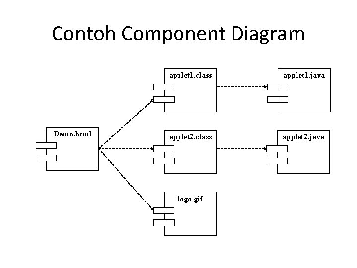
Implementation Diagram. Atau hal-hal fisik dari sistem yang akan dimodelkan dan ada ketika sistem dieksekusi. Jadi Diagram komponen atau component diagram dibuat untuk mengambarkan struktur dan ketergantungan antara kumpulan komponen dalam sebuah sistem.
Komponen dapat digunakan untuk mendefinisikan ukuran dan kompleksitas sistem SW. UML mempunyai 9 diagram yaitu. Now thanks to the ConceptDraw DIAGRAM diagramming and vector drawing software extended with ATM UML Diagrams Solution from the Software Development Area you can design without efforts any type of Bank UML Diagram you want - Class Activity Communication Component Composite structure Deployment Interaction overview Object Package Profile Sequence State machine Timing Use case.
The UML has two kinds of implementation diagrams. Komponent dapat berupa source code komponent biner atauexecutable component. Deployment diagram adalah salah satu model diagram dalam UML untuk mengerahkan artifact dalam node.
Demikian pembahasan tentang Pengertian Component Diagram. Dennis Alan and Co. Aktifitas lainnya seperti use case atau interaksi.
Deployment diagrams are typically used to visualize the physical hardware and software of a system. A deployment diagram is a UML diagram type that shows the execution architecture of a system including nodes such as hardware or software execution environments and the middleware connecting them. A step by step approach.
Fungsi Simbol dan Contohnya. Jarungjit Parnjai Last modified by. An Introduction to Object-Oriented Analysis and Design and Iterative Development Third Edition Book.
--An MPW C compiler warning Objectives Summarize UML deployment and. Behavioral Diagrams - StateTransition Subject. UML Component and Deployment Diagrams is the property of its rightful owner.
In this component diagram tutorial we will look at what a component diagram is component diagram.

Uml Diagram Adalah Pengertian Jenis Lengkap Dengan Contohnya Studi Elektronika

Diagram Class Diagram Objek Diagram Component Dan Deployment

Chat Portal Project Diagrams Software Ideas Modeler In 2021 Chat App Chat Portal
Uml Diagrams Jung Woo What Is Uml Standard

Uml Component Diagram Component Diagram Diagram Data Science
Component Deployment Diagram Ppt Download

Component Diagram For Bas Left And Class Diagram For Bas Right Download Scientific Diagram

What Is Unified Modeling Language Uml Activity Diagram Component Diagram Class Diagram

Billing System Uml Component Diagram Component Diagram Computer Programming Diagram
State Transition Diagram Ppt Download
Component Deployment Diagram Ppt Download
Uml Tutorial Use Case Activity And Sequence Diagrams Essential Software Modeling Start With A Use Case And El Sequence Diagram Diagram Learning Science

Uml Dan Pembahasan Pemograman Berorientasi Objek Rizky Luthpiyana If15d120

Uml Dan Pembahasan Pemograman Berorientasi Objek Rizky Luthpiyana If15d120

Uml Dan Pembahasan Pemograman Berorientasi Objek Rizky Luthpiyana If15d120

Uml Dan Pembahasan Pemograman Berorientasi Objek Rizky Luthpiyana If15d120

E Commerce Microservices Uml Deployment Diagram Deployment Ecommerce Diagram
Pertemuan 12 Package Diagram Deployment Diagram Deployment Diagram
Uml Process From Requirement Software Requirement Requirements Engineering


0 Comments